 we have taught you well my friend!
On to business as usual, the second enclosure has been operated to change out the MLV + neoprene for butyl rope. Still got to get a new impedance curve and then on to an impedance correction network.
I noticed I'm approaching 200.000 views on this thread
, based on the start date that works out to close to 300 views a day! I'm honored and a little proud! Those views can't be mine alone (lol).
Thanks mate!
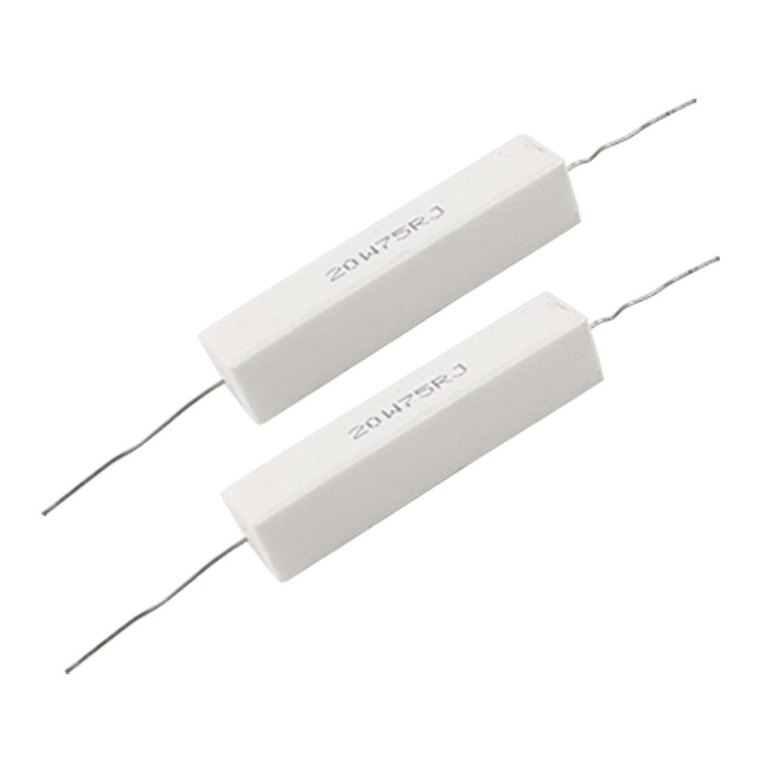
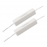
A question I hope to get answered... I need pretty big resistors with good power handling.
Do I parallel multiple ceramic type resistors to up the power handling or would a wire wound resistor work for a big Zobel like network.
I'd expect the wire wound resistor type to act somewhat like an inductor. More so than a typical ceramic resistor would? But good power handling is necessary.
I guess the ceramic ones are still wire wound but I could parallel 5x 100 ohm 20 watt to get one ~100 watt 20 ohm resistor that way.
5 x 75 ohm 20 watt parallel to get 15 ohm etc.
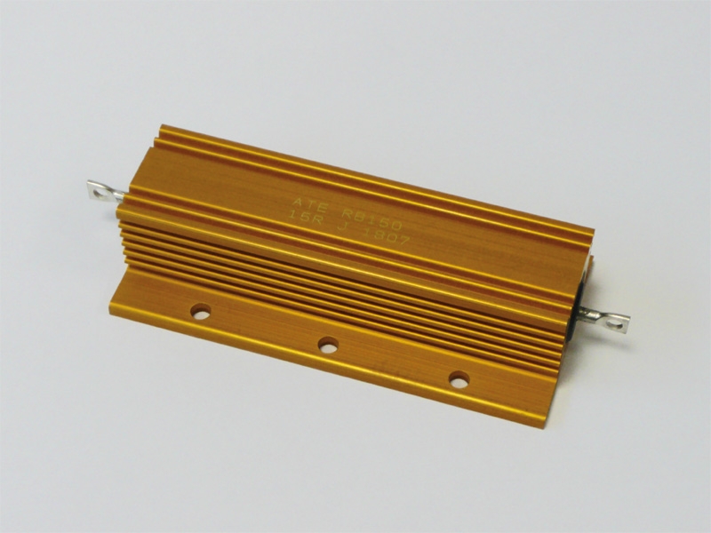
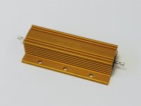
Or would these work as well:
Any help?
For capacitors I'd go for MKP and inductors an iron core would probably be fine for this particular job as long as it's power handling is up to the task. I'm definitely open for suggestions here...
A question I hope to get answered... I need pretty big resistors with good power handling.
Do I parallel multiple ceramic type resistors to up the power handling or would a wire wound resistor work for a big Zobel like network.
I'd expect the wire wound resistor type to act somewhat like an inductor. More so than a typical ceramic resistor would? But good power handling is necessary.
I guess the ceramic ones are still wire wound but I could parallel 5x 100 ohm 20 watt to get one ~100 watt 20 ohm resistor that way.
5 x 75 ohm 20 watt parallel to get 15 ohm etc.
Or would these work as well:
Any help?
For capacitors I'd go for MKP and inductors an iron core would probably be fine for this particular job as long as it's power handling is up to the task. I'm definitely open for suggestions here...
Attachments
Last edited:
Sorry to post in this thread, but I know you guys have been through this and can help me out.
I'm planning to start a DRC thread fairly soon (computer audio forum?) with custom scripts/config files and a text guide. Hang in there and stay tuned...
Don't use DRC to make the sweep.
Use REW and make a 1M sweep. You will also get your FR curve.
Go to File, Export, and export as wav, 32-bit, don't normalise the peaks.
Now, you will need to convert that wav file into pcm. Wesayso uses CoolEdit, I use XLD.
Now, rename the new pcm files as LeftSpeakerImpulseResponse44100.pcm and RightSpeakerImpulseResponse44100.pcm (assuming you made a 44100 sweep.
Put those 2 files in the folder "sample", which is inside the folder drc-3.2.0
Open DRCDesigner, and make the target curve as you see fit.
Go to the filter tab and start off with the presets. Get DRC to make all the filters. They will be in the folder "ConvolverFilters" when it's done.
Now, going back to REW, use an output where you can add the convolution filters (try the preset Minimal at first). If you have JRiver, you can open a "Live" session, where JRiver will capture the output from your PC and add the processing you've selected. (If you don't know how to do this, there are some how-to's online... I don't have Windows at the moment and I forgot all the exact steps.... sorry.)
Once you know your output is using the filters, you do another sweep with REW. Now, you will be able to compare the first sweep, to the sweep you just made. Change the preset filter to another (Normal, for example) and try another sweep.
Also, listen to some music and do A/B listenings with and without the filters to see which one sounds better to your ears.
Hope it makes sense... if not, ask again and I'll try to explain it better.
Thanks perceval!
Wesayso, Hope you'll indulge me a little more. Just one last set of questions to both of you:
- From perceval's response, it seems at no point does DRC write out the frequency response. Is that correct? I was hoping to see how the response looks after applying a continuously widening time window with reducing frequency. Holm has a similar function, but it just breaks it into three sections, 10000 Hz, 1000 Hz and 100 Hz, IIRC.
- I have JRiver and I'm familiar with the live playback process and measuring the convolved response. So, the only thing I get out of DRC are the correction filters, correct?
Thanks mate!
A question I hope to get answered... I need pretty big resistors with good power handling.
Do I parallel multiple ceramic type resistors to up the power handling or would a wire wound resistor work for a big Zobel like network.
I'd expect the wire wound resistor type to act somewhat like an inductor. More so than a typical ceramic resistor would? But good power handling is necessary.
I guess the ceramic ones are still wire wound but I could parallel 5x 100 ohm 20 watt to get one ~100 watt 20 ohm resistor that way.
5 x 75 ohm 20 watt parallel to get 15 ohm etc.
Or would these work as well:
Any help?
For capacitors I'd go for MKP and inductors an iron core would probably be fine for this particular job as long as it's power handling is up to the task. I'm definitely open for suggestions here...
Or look around for incandescent light bulbs with appropriate R's.
Thanks perceval!
Wesayso, Hope you'll indulge me a little more. Just one last set of questions to both of you:
- From perceval's response, it seems at no point does DRC write out the frequency response. Is that correct? I was hoping to see how the response looks after applying a continuously widening time window with reducing frequency. Holm has a similar function, but it just breaks it into three sections, 10000 Hz, 1000 Hz and 100 Hz, IIRC.
- I have JRiver and I'm familiar with the live playback process and measuring the convolved response. So, the only thing I get out of DRC are the correction filters, correct?
Trough DRC designer you usually only create the correction filter. But if you want to check out the resultant frequency response prior to checking it by measuring you can.
DRC Designer creates batch files, in the X:\DRCDesiger folder. X being whatever drive you installed it in. Look for the "drcWrapperRunDRCLeftcustom_44100.bat" and a similar one for the right channel. If you edit that batch file, look for: "PSOutFile" it will be followed by something like "=LeftSpeaker44100CUSTOM_X.pcm".
Change only "PSOutfile" into "TCOutfile" and run the batch file. It will create the PCM file in the X:\DRCDesigner\Convolverfilters directory. Convert that PCM file to a 32 bit wav and you can import it in REW to check it out. It will be a prediction (and a very good one at that) of the frequency response after correction. Is that what you wanted to see?
The .txt files in that same X:\DRCDesigner directory contains all the info about the chosen windowing etc. With a bit of calculation you can convert the numbers there to cycles or ms. Just run a standard Normal template and look what that gives you. Not in the custom tab though, as those windows will be slightly off.
On to business as usual, the second enclosure has been operated to change out the MLV + neoprene for butyl rope. Still got to get a new impedance curve and then on to an impedance correction network.
I noticed I'm approaching 200.000 views on this thread
Impedance matching network, as in Zobel? With active speaker?
It will be a prediction (and a very good one at that) of the frequency response after correction. Is that what you wanted to see?
No, I wanted to see the response before correction.
Somehow I got it into my mind that DRC has a continuously widening window as the frequency gets lower. Maybe it was one of your posts. As far as I know, no other software does this.
The output that you mention will be an impulse, correct? It still won't give me the frequency response as measured by DRC, i.e., using a small time window in HF and continuously increasing time window as frequency gets lower.
I can take the response as a pm, don't want to digress from your main topic here.
For speakers in domestic usage, you don't need resistors of that much power rating in Zobel.
Anything 3-5W in your drawer would do. I've used 2W in some occasions and they work fine. They never get warm, never fail. (what if they fail? it's alright, just open like a fuse, no hazard)
If the resistors in passive xover get hot and burned-out (in a properly designed speaker/network), you will loose your hearing already. Then it doesn't matter anyway.
Or would these work as well:
These particular resistors are intended to be chassis mounted (metal chassis for heat transfer)
Yes indeed... with active speakers. Strange huh?
Zobel is across driver terminals, and thus directly across amplifier terminals via speaker wire in active system. All this does is dump power.
These particular resistors are intended to be chassis mounted (metal chassis for heat transfer)
True, but without it they will be able to withstand about half of their full power rating. Which will be more than enough for testing.
For speakers in domestic usage, you don't need resistors of that much power rating in Zobel.
Anything 3-5W in your drawer would do. I've used 2W in some occasions and they work fine. They never get warm, never fail. (what if they fail? it's alright, just open like a fuse, no hazard)
If the resistors in passive xover get hot and burned-out (in a properly designed speaker/network), you will loose your hearing already. Then it doesn't matter anyway.
I'm not compensating for one 10 watt driver here. I have 25 a side that I look at as one big 240 watt driver. The biggest load will be at the low frequencies. Higher frequencies will be a very small load in comparison. Most of the entire speaker will not see any more than those 2 watt. That is correct. But in bass frequencies there is a lot more with about 15 dB of boost.
Zobel is across driver terminals, and thus directly across amplifier terminals via speaker wire in active system. All this does is dump power.
It's not a zobel for a driver, but for a speaker. It will be over speaker terminals. Look a few pages back in the thread.
No, I wanted to see the response before correction.
Somehow I got it into my mind that DRC has a continuously widening window as the frequency gets lower. Maybe it was one of your posts. As far as I know, no other software does this.
The output that you mention will be an impulse, correct? It still won't give me the frequency response as measured by DRC, i.e., using a small time window in HF and continuously increasing time window as frequency gets lower.
I can take the response as a pm, don't want to digress from your main topic here.
So basically you want to see the filtered response window, that DRC uses to generate the impulse correction.
Audiolense and Acourate also work with frequency dependent windowing as far as I can tell. This might be a good question to ask in gmad's new thread. I haven't looked to retrieve that window prior to correction and usually look at the results in a manual way in REW. Would be fun to be able to export it though. Both before and after correction.
Here's the new thread with also very good working templates (Better than the standard ones) from gmad: http://www.diyaudio.com/forums/full-range/275730-convolution-based-alternative-electrical-loudspeaker-correction-networks.html
Have many resistors of various types including the ones shown above. Yet the frugel diy part of me says make your own from pencil leads. Have a peak over at Troels. He has a nice writeup on how to make your own.
I remember reading about that. Might be fun to look into
. Thanks!I'm not compensating for one 10 watt driver here. I have 25 a side that I look at as one big 240 watt driver. The biggest load will be at the low frequencies. ...
The Zobel is a cap in series with a resistor, right?
So the LF is largely blocked by the cap, there won't be high current of LF going through the resistor.
What are the value of R and C? By which you can calculate at what frequency the C starts dominating the whole impedance of the string.
- Home
- Loudspeakers
- Full Range
- The making of: The Two Towers (a 25 driver Full Range line array)