20th December 2008, 10:12 PM #9
MJK
Re: Re: MLTL v. ML TQWT
So a quarter wave enclosure can be defined by a length, an area at the closed end S0, and an area at the open end SL. Assuming that the area varies linearly between S0 and SL (this is a simplification for this discussion, the area could vary exponentially or conically without impacting the explanation) then the resonant frequencies of the 1/4. 3/4, 5/4, .... are defined by these three geometric values. Mass loading refers to an intentional severe restriction placed at the open end that dramatically reduces the area from SL. This restriction can be a round port, a square or rectangular opening, or a narrow slot. The length of the restriction can be just the wall thickness of the enclosure or it can be significantly longer. The mass loading refers to the slug of air in the restriction since it acts like a concentrated moving mass. The benefit of mass loading a quarter wave enclosure is that it can now be made shorter in length for the same tuning frequency and the slug of air that is the mass load tends to reduce the output from the harmonics of the fundamental standing wave that is used to augment the bass output of the system. The fiber damping does not provide any mass load, it just provides damping of the internal standing wave resonances of the air in the enclosure.
Mass loading can be applied to a tapered TL, a straight TL, or a expanding TL which is commonly refered to as a TQWT. It works by the same principle for each geometry. In my opinion one geometry is not better then the other two if the designs are done correctly. Optimum driver position is a finction of the shape of the enclosure and the driver is typically placed at about 0.5 x L for a TQWT and between 1/3 to 1/5 x L for a straight or tapered TL. Depending on the degree of taper or expansion there will be an optimum position for the driver that will minimize the output from the higher harmonics.
Therefore, I would go for the Sony MLTL over PappasTL specially since it has the flexibality to be tuned by the port.
Vix,
The difference between a MLTL and a horn is when you hear a back loaded horn you dance the ball room with your partner while when you play the same music through MLTL you tend to shake your body to disco movements to what you feel through your body. My dream is to try and come as close as possible to that goal with the full ranger 206 by augmenting the lower bass to tame the excess mids and reach an excited state to escape from the usual boaring mellow moods
Now dont tell me to switch on my subwoofers which I packed away long time ago.
May be I am trying the impossibe, but thats what DIY is for!
john.
John,
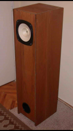
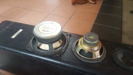
This is my MLTL with Fostex FE206e, a long time ago (2005 maybe). I could not get the sound I wanted from that one, as it is not a "natural" box for that driver; it is much better suited to Fe207.
So, I just dont't want that you go through the hassle of building a TL of any sort with Fe206, only to be disapointed. Either build a horn, or find another, more suitable driver. By the way, it did go low, but sounded thin in the upper bass...
Attachments
By the way, it did go low, but sounded thin in the upper bass...
Good point Vix... if the cabinet is tuned too low/incorrectly then the mid-bass tends to suffer - software modelling shows the same.
Hi Vix,
Does your cabinet have a folded TL inside it?
Look at the drawing at post #54 where I have drawn the Sony cabinet. It contains folded chamber of length of 95" or so.
To create that you need to have a separator inside the cabinet separating the front and back chambers with a fold at the top and a port at the bottom.
I think this long line is responsible for the low to mid bass frequencies in the Sony box.
If you have the drawings or measurements of your cab please give it here so that I will keep away from repeating the same design.
regards,
john.
Hi Vix,
Does your cabinet have a folded TL inside it?
regards,
john.
Nope. It is an ML TL. The drawing used to be here:
Quarter Wavelength Loudspeaker Design
I no longer have them

Hi phivates & Vix,
I thought as much.
Thats the box I am using currently with the 206.
I have tried many different boxes wich I came across with 8" hole with the 206.
The above box is the only one which came close to my expectations.
But it has a major flaw as you need mid rang attenuation to use with 206.
The plans, the BSC, and the description is found in the link bellow.
Project 5 : Virtual Fostex FE-206E and FE-207E ML TL Design
I think using a cab like the Sony SS-TL40 will correct all the flaws inherent to the 206.
Looks like no one is prepared to test the above box for me with the software.
I am scared to replace a driver of Sd= 206cm into a cab designed for Sd= 156cm.
Your valued response is most wellcome.
john.
Nobody is 'unprepared' but you may wish to reflect on the fact that we do not all have unlimited time. I started typing something yesterday, but frankly, I have work to do, and after half an hour I had to give up. However, I have ten minutes spare, so I'll do my best to cover some aspects.
Firstly, here is the FE206En (factory data) in your Sony TL, with the dimensions you provided a few posts back. 1/2 space FR, impedance & RMS driver deflection; left hand column shows undamped response for clarity of line behaviour, right hand shows same with light damping equivalent to what is typically used in such boxes in the first two manifolds.
There are a lot of erroneous assumptions & pronouncements above, so here are some engineering facts.
-The FE206En (& variations of the 206) were specifically intended for use in back-horns with a high output impedance amplifier, or similar compensation applied via series R &c. They have a rising on-axis response above ~ 1KHz to enhance off-axis dispersion and are not intended to be listened to directly on-axis unless you happen to like an elevated HF.
-Much of the 'slam' or 'punch' referred to in classical & particularly rock music is found in the octave 60Hz - 120Hz.
-For a given tuning & volume, a TL has a higher, not lower, F3 than an equivalent vented box.
-A TL cannot 'correct' for driver characteristics that exist well above the enclosure's operating BW. No back load can, with certain exceptions for compression horns that significantly load & alter the resonant profile of the diphragm & suspension, and in their case it's more 'alter' than 'correct for'.
-Sd has no direct connection to line CSA in a TL / QW enclosure. Like any other kind of vented box, Qt, Fs and Vas dominate. So you should not be 'scared' of putting a totally different driver into some other random box just because of a difference in size. You should be 'scared' for other reasons, but that one comes some way down the list of problems.
-The line you have drawn is tuned to roughly the low-mid 30Hz regions, and combined with its highly damped characteristics (using the factory data) has a highly damped LF response at some -6dB. This tuning is lower than the driver is suited to, especially for the available volume, unless it is picking up significant assistance from amplifier, room modes or similar. Rooms are the greatest variable in the entire sound reproduction chain, and different enclosures interact with them in different way, so beyond a certain point, this cannot be predicted with particular accuracy.
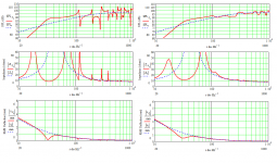
Attachments
Last edited:
FWIW, up until fairly recently [and probably still the norm in most venues], prosound systems, which we know has plenty of 'slam' [true 'chest thump' is down in the ~20-35 Hz BW], were set up to be ~ -24 dB/40 Hz and ~flat from 80-300 Hz, so a ~56 Hz tuned 'scoop bin' [BLH] with a~ 300 Hz mass corner and at least a +6-10 dB gain [depending on room acoustics] seems the goal here.
The FE206en theoretically has plenty of motor, so little/no series resistance should be required and if true 'chest thump' is required, then that's what a separate sub system is for, though one's home needs to be well built to handle the extremely high SPL and sound deadening required [THX LFE reference at minimum].
GM
Sounds favourite to me. The existing amp is supposed to be a 6550 PP, so output impedance will probably be in the ~0.75ohm - 1.5ohm region, & with an Andy Grove designed 300b SET apparently in the offing, that's probably going to rise to somewhere around 2.5ohm - 4ohm. Some Ni80 resistance wire might be cheaper to get what little series R should be needed -doesn't look as good on the rack though.
The existing amp is supposed to be a 6550 PP, so output impedance will probably be in the ~0.75ohm - 1.5ohm region, & with an Andy Grove designed 300b SET apparently in the offing, that's probably going to rise to somewhere around 2.5ohm - 4ohm. Some Ni80 resistance wire might be cheaper to get what little series R should be needed -doesn't look as good on the rack though.
Last edited:

- Status
- This old topic is closed. If you want to reopen this topic, contact a moderator using the "Report Post" button.
- Home
- Loudspeakers
- Full Range
- Pappa's TL