IN-THE-WALL BACK LOADED HORNS
-The enclosures will be behind decorative wood panels on the front.
-Each .75” plywood enclosure is about 21”x 87”x 3.5” inside.
-The drivers will be Fostex Fe166e.
-The horn compression chamber size, throat area and expansion rate will roughly resemble the Austin A-166 by Ron Clarke. But horn length will be about 160”.
-Due to the length of the cabinets there will be just one major fold, putting the horn mouth near the driver cone, and these both will be in plane with the wall of the room on which they mount.
-The distance to the ceiling is: 5”(driver) and 20” (horn mouth); with each about 25” from the side walls.
-Below the speakers are to be 68” high wardrobe cabinets, that is why the speaker drivers are so close to the ceiling.
- Bedroom usage and appearance are driving this design, but I do want the sound to be great, if possible.
I figure that there will be little or no baffle step loss, and good planar support for the bass response---hopefully not too much.
On the other hand, phase coherence/imaging may suffer due to all of the reflective surfaces near the drivers.
I will likely want to point the drivers down at an angle into the room, and maybe toe them in a bit.
I am picturing wooden mounts, not much bigger around than the drivers themselves, that would bring the drivers out from the wall (panel) surface.
I am wondering if it would help imaging to bring the drivers out from the wall a few inches, any ideas?
How far would they have to get from the wall to benefit imaging?
Theoretically: Would flush mounted speakers in the middle of large wall, without closely adjacent surfaces tend to image OK?
Thanks, Howard
Howard,
This sounds really interesting and I have often wondered about embedding a nice speaker between the drywall and studs in a home. We are about to build a new home so I may actually have an opportunity to do this - drywall board is actually a great material to build a horn speaker with. I want to take a crack at simulating this in akabak with the angled ceiling placement even. I just looked at the Austin II plans and see that the horn mouth is 8 in x 15 in but your size constraint is 21 in x 3.5 in. Is the 3.5 in dimension the depth of the speaker in the wall due to the joist depth (2x4 timber) or is it 21 in? I am assuming 3.5 in deep x 21 in wide x 87 in high. The mouth aperture will have to be 21 in wide x 7.1 in tall. The expansions will have to be along a direction parallel to the wall since you are limited by the wall depth of 3.5 in. Basically I am envisioning a flattened wall horn. One thing to keep in mind is that the max dimension of 3.5 in may limit the lower bass extension as it can only accommodate a maximum wavelength size in one dimension. It may result in a cupped sound. Before I start, I just want to confirm that I am correct in assuming that your max speaker depth is 3.5 in.
Regards,
X
The Austin A166 only has a 127 in path, do you really want a 160 in path? Also if 3.5 in depth is max and 21 in width is max, the largest CSA for the mouth will only be half of the Austin due to 3 in wide clearance required for throat passage from driver chamber above the mouth. So bass gain will only be about half of the Austin. You will have a +9dB gain due to corner loading so I don't think it will be an issue but I can already see that this won't look anything like the Austin due to geometrical constraints. Basically I will design a custom in wall horn with FE166 driver.
Just a minor reminder guys: as you are no doubt aware the Austin and Dallas horns were not designed using the 1-dimensional wave equation (for that matter, FH3 wasn't entirely either). If you are looking at them purely from that basis, you will not actually understand why they are the way they are. Changing the aspect ratio for e.g. is a significant performance departure / compromise.
Last edited:
Initial Design of In-Wall BLH for FE166EN
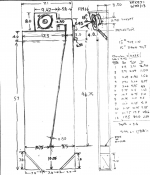
Here is what I came up with for a design so far: A 4.33 liter driver chamber connected to a 129 in long conical horn with a throat area starting at 10.15 sq in and expanding to a 70 sq in mouth area. The driver is canted 15 deg toe-in and 15 deg down and is located 5 in from the ceiling. The horn mouth is located immediately below the driver box and has a 4 in tall x 17.5 in wide opening.
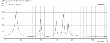
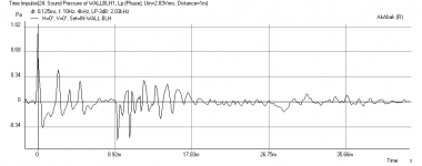
The simulation in AkAbak assumes corner mounting 25 in away from the side wall. The corner loading provides a huge bass gain of +9 dB. First plot is frequency response at 1 m, the bass peak is about 105 dB at 1 watt input. The next plot is the zoomed into 1 kHz, then next plot is impedance, then the cone displacement (exceeding xmax of 1 mm already so I don't think there is enough horn loading due to lack of expansion ratio), final plot is the impulse response showing a significant group delay beyond the audible 8 ms range. The bass extension is pretty deep (90 dB at 27 Hz) - but it is not flat.
This design can definitely use some tweaking - and I would love to receive feedback/constructive comments to improve design. It probably would sound not too bad given the size constraint and that it is in-wall, certainly better than any box-store in wall speaker you can buy. The sensitivity with the FE166EN is phenomenal - perfect for fleawatt tube amps.
Here is what I came up with for a design so far: A 4.33 liter driver chamber connected to a 129 in long conical horn with a throat area starting at 10.15 sq in and expanding to a 70 sq in mouth area. The driver is canted 15 deg toe-in and 15 deg down and is located 5 in from the ceiling. The horn mouth is located immediately below the driver box and has a 4 in tall x 17.5 in wide opening.
The simulation in AkAbak assumes corner mounting 25 in away from the side wall. The corner loading provides a huge bass gain of +9 dB. First plot is frequency response at 1 m, the bass peak is about 105 dB at 1 watt input. The next plot is the zoomed into 1 kHz, then next plot is impedance, then the cone displacement (exceeding xmax of 1 mm already so I don't think there is enough horn loading due to lack of expansion ratio), final plot is the impulse response showing a significant group delay beyond the audible 8 ms range. The bass extension is pretty deep (90 dB at 27 Hz) - but it is not flat.
This design can definitely use some tweaking - and I would love to receive feedback/constructive comments to improve design. It probably would sound not too bad given the size constraint and that it is in-wall, certainly better than any box-store in wall speaker you can buy. The sensitivity with the FE166EN is phenomenal - perfect for fleawatt tube amps.
Attachments
Last edited:
I am glad to see that there are others that find this idea intriguing. For some it might be the only way their spouse would accept a large horn in a shared space. I will try to remember to take pictures of the insides of the horns to share later. One will lay horizontally, and one will stand vertically, due to space/design constraints. So they will be different, but will hopefully perform similarly.
I know that I am not conforming to the A-166 design closely, but it is good to have a guide for the CC and throat sizes. That said, I am very interested, if not technically educated, about what makes a good horn do what it does.
In the past I have mostly taken hints from successful/popular designs, and then done rough builds to test out my designs. My successful tweaks have largely come by trial and error.
Xrk971 , If I was working with a deeper stud bay, like 5.5”, that might make things easier-maybe you could make yours deeper. Probably best to avoid exterior walls, due to heat and moisture issues. Maybe if the FE166e's don't work out, I could use a pair of 126e's that I have-but I would not want to do a total redesign at this point if I can avoid it.
The mouth of the A166 is about 8x15, but the cross-section immediately before the mouth is 7.3x7.9, which is about the same as my 3.5x17 (21 minus 3.25-throat- minus .75-divider). So maybe my horn's mouth could somehow have a rapid expansion like that of the A166. Also the horn mouth will be unloading right onto the top of a 20” deep cabinet top-which I think will effectively be an extension of the horn mouth.
It would not be hard to shorten the horn, if it came to that. Does anybody know what one might expect with a horn that is 30” longer than the A166? I could experiment pretty easily I think, because the horn is like an open flat box on the workbench, and the top that closes it up has the mouth cut-out in it. So just move the cutout, and close off the last 30” of horn. If the final piece were to be shortened, the internal baffling, which is super simple, could be adjusted/optimized.
SCOTTMOOSE SAID: “Just a minor reminder guys: as you are no doubt aware the Austin and Dallas horns were not designed using the 1-dimensional wave equation (for that matter, FH3 wasn't entirely either). If you are looking at them purely from that basis, you will not actually understand why they are the way they are. Changing the aspect ratio for e.g. is a significant performance departure / compromise”.
I will have to look up “1-dimensional wave equation “, as I don't know about it! I actually started this project less hopeful about getting actual horn performance, thinking that I would end up with some sort of restricted mouth, mass loaded transmission line (MLTL).
Here is an interesting question: What would happen if the aspect ratio was made roughly 1:1 by creating 4 separated channels in last 60” of expansion(which would also greatly reinforce the larger panels in this area)? The channels might be 3.5 x 4, or 3.5 x 3.5, or 3.5 x 3, for example, and would expand as they progressed towards the mouth. Kind of like a sectoral horn.
Sounds like maybe each of the small pathways would prevent the propagation of larger wave-froms, and thus the lower,louder bass frequencies, is this the concept?
I am not sure if this option has been considered but I found it very interesting...
http://www.diyaudio.com/forums/multi-way/217298-square-pegs.html
Its worth reading the whole thread...
http://www.diyaudio.com/forums/multi-way/217298-square-pegs.html
Its worth reading the whole thread...
Last edited:
Hi xrk971, thanks for using my parameters in your simulation. Any chance that my extra 30" of length would help load the driver and limit excursion (in place of a greater expansion ratio)? Is there any indication that this is operating as something other than a horn(a TL or other tuned pipe, like most compromised designs apparently do)? Like maybe the peaks and valleys in the amplitude.
I tested a previous prototype with a sweep tone from 20 hz, and it actually sounded pretty smooth, with only slightly up/down noticeable variations in volume through the swept range.
Your drawing is extremely similar in important detail, and overall layout to my in-progress speaker, except that I have built in the 30" of extra length.
Simplifying like mad, in essence, the 1d wave equation assumes plane-waves unless otherwise adapted, i.e. that the wavefront is flat. It's (extremely!) useful & functional, but doesn't always cover all aspects of design, since the wavefront technically may be better thought of as an expanding bubble.
Add extra 30 inches + restrict terminus
Howard,
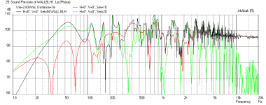
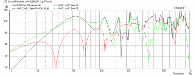
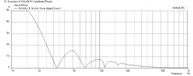
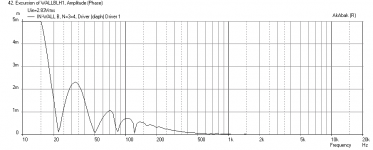
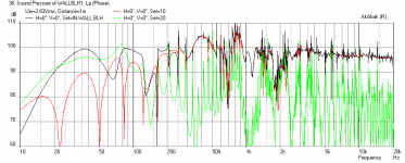
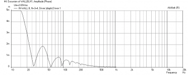
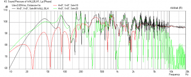
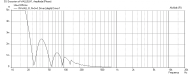
Here is sim with 30 inches more - it helps smooth response and gets deeper extension. However, the peak excursion is just pulled to lower frequency. I tried restricting terminus to a 1.30 x 4 in hole and this smooths even more but peak excursion actually worsens. I then tried adding a horn extension to get the final expansion ratio to be similar to Austin with additional 12 inches of exponential exit horn - and this still does not reduce cone excursion. The solution may lie in the chamber and throat more.
First plot is freq response with +30 inches in main lengths, second is corresponding cone excursion.
Third plot is freq response with +30 inches and restricted terminus and corresponding excursion.
Fifth plot is freq response with +30 inches and 140 sq in mouth x 12 in long exponential external horn and corresponding excursion.
I think with stuffing to damp the resonances more like a TL, you may be able to get this to sound pretty good. The cone excursion is an issue still.
Howard,
Here is sim with 30 inches more - it helps smooth response and gets deeper extension. However, the peak excursion is just pulled to lower frequency. I tried restricting terminus to a 1.30 x 4 in hole and this smooths even more but peak excursion actually worsens. I then tried adding a horn extension to get the final expansion ratio to be similar to Austin with additional 12 inches of exponential exit horn - and this still does not reduce cone excursion. The solution may lie in the chamber and throat more.
First plot is freq response with +30 inches in main lengths, second is corresponding cone excursion.
Third plot is freq response with +30 inches and restricted terminus and corresponding excursion.
Fifth plot is freq response with +30 inches and 140 sq in mouth x 12 in long exponential external horn and corresponding excursion.
I think with stuffing to damp the resonances more like a TL, you may be able to get this to sound pretty good. The cone excursion is an issue still.
Attachments
-
 Wall-BLH-Long-Displ-1m-External-Exp-horn.png25.7 KB · Views: 38
 -
 Wall-BLH-Long-Freq-1m-External-Exp-horn.png36.1 KB · Views: 272
 -
 Wall-BLH-Long-Displ-1m-restrict-terminus.png25.8 KB · Views: 279
 -
 Wall-BLH-Long-Freq-1m-restrict-terminus.png37.4 KB · Views: 275
 -
 Wall-BLH-Long-Displ-1m.png25.9 KB · Views: 279
 -
 Wall-BLH-Long-Freq-1m.png35.4 KB · Views: 567
Swap with Alpair 10.2 driver
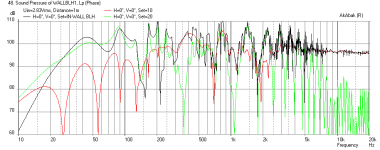
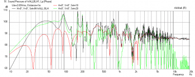
If you use the MA Alpair 10.2 driver, the cone displacement is not an issue and you still get lots of bass but the mids and HF are not high enough to keep up with the extensive bass.
If you use the MA Alpair 10.2 driver, the cone displacement is not an issue and you still get lots of bass but the mids and HF are not high enough to keep up with the extensive bass.
Attachments
Thanks again xrk971 for simulating! It would be kinda amazing to end up with truly low bass from these speakers. If they also had good bass transients-wow! Won't have the punch of a large, top-quality, woofer I don't imagine, but small drivers/horns are a different experience.
I notice a dip around 160hz in the graph. I had a similar dip with a back horn I designed/made for the Fostex FE126e. Got rid of the dip by drilling a 1” hole from the comp chamber into the expansion about 50” down a 75” line (drilling the hole: just a hunch arising out of a pervading sense of frustration). Maybe the hole effectively changed the CC volume? Also ended up closing the horn mouth down to about 13 sq in, making the thing into a mass loaded pipe that still had a compression chamber. Won the single driver division in the 2008 PNWAS speaker contest with these speakers. Those “horns” are 32” high, taper from 12” at the top to 17” at the bottom and are 6” deep, with the mouth/port on the side, and driver on the face. The really rock for the size of the driver. I set them up in very large room (30x40', with 20' tall ceiling, powered by a mid 60's Sony 20 watt receiver ) and totally rocked the place----which of course will make me sound like I am exaggerating. I think that the balcony location with the sloping ceiling close above helped with a sort of amphitheater type of situation. Too bad the homeowner became another victim of the recession- he seemed about ready to hire me to make him a cool system for that space.
I also built a 3x deeper version that retained the horn mouth-now firing at the floor- using a FE206e and a SEAS passive radiator on the back side of the CC, facing backwards. Good bass from the PR and the horn! Maybe a PR used like this makes the CC effectively larger. Not sure how it would effect excursion.
Howard,
You are welcome. I am surprised by how deep the bass is with the FE166EN, I think the powerful motor allows it to just womp out the low frequencies given a sufficient horn length to amplify. The cone excursion exceeds the limit, but run at softer levels. Your idea of drilling a hole is actually very good and can be modeled very accurately with Akabak - I had the same idea but to strategically place multiple holes to really flatten the response in a TL. Look at my 'Flute Pipe TL' thread. http://www.diyaudio.com/forums/full-range/237384-flute-pipe-tl.html Basically, the holes serve as de-Q'ing devices to spoil a particular resonance frequency. I am interested in the speaker you describe that won the competition and rocked the house, do you have photos or drawings of the plan or layout? Sounds very cool.
You are welcome. I am surprised by how deep the bass is with the FE166EN, I think the powerful motor allows it to just womp out the low frequencies given a sufficient horn length to amplify. The cone excursion exceeds the limit, but run at softer levels. Your idea of drilling a hole is actually very good and can be modeled very accurately with Akabak - I had the same idea but to strategically place multiple holes to really flatten the response in a TL. Look at my 'Flute Pipe TL' thread. http://www.diyaudio.com/forums/full-range/237384-flute-pipe-tl.html Basically, the holes serve as de-Q'ing devices to spoil a particular resonance frequency. I am interested in the speaker you describe that won the competition and rocked the house, do you have photos or drawings of the plan or layout? Sounds very cool.
I will look into my papers and see if I can find the drawings. I was not taking pictures at the time. Was thinking about opening up the cabs at some point soon-like by August, when I clean them up with a nice real-wood wrap. I thought there was a picture on the pnwas site, under Events, 2008 Speaker Contest, but the pdf file doesn't open for me now.
- Status
- This old topic is closed. If you want to reopen this topic, contact a moderator using the "Report Post" button.
- Home
- Loudspeakers
- Full Range
- In-the-Wall Back Loaded Horns