just trying to create a ML-TL for a new 15" coax driver.
L - 155cm
Zdriver - 40cm
Zport - 142.5cm
So - 3500cm2
Sl - 3500cm2
port - 50x12.5cm
port length - 5cm
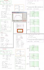
gives me this
which is ok on face value.
the problem is the footprint and volume are pretty big, over 500 litres, which pushes it into tannoy GRF territory. If i have 500 litres to play with, can i do 'better' than this, i.e extension and uniformity?
is there anyway to keep that kind of level of performance but shrink the overall footprint and/or volume back down to say sub 300 litres?
driver T/S is.
Fs - 47.7
Re - 5.2
Le - 1.4mh
BL - 19.2
Sd - 990cm2
Vas - 148.7ltr
Qed - 0.36
Qmd - 6.15
Qtd - 0.34
mounting depth is 22cm, frame size is 40cm.
any suggestions and input are most welcome.
L - 155cm
Zdriver - 40cm
Zport - 142.5cm
So - 3500cm2
Sl - 3500cm2
port - 50x12.5cm
port length - 5cm
gives me this
An externally hosted image should be here but it was not working when we last tested it.
which is ok on face value.
the problem is the footprint and volume are pretty big, over 500 litres, which pushes it into tannoy GRF territory. If i have 500 litres to play with, can i do 'better' than this, i.e extension and uniformity?
is there anyway to keep that kind of level of performance but shrink the overall footprint and/or volume back down to say sub 300 litres?
driver T/S is.
Fs - 47.7
Re - 5.2
Le - 1.4mh
BL - 19.2
Sd - 990cm2
Vas - 148.7ltr
Qed - 0.36
Qmd - 6.15
Qtd - 0.34
mounting depth is 22cm, frame size is 40cm.
any suggestions and input are most welcome.
That slight depression around 60Hz and very slight peak at 35Hz looks like the enclosure might be somewhat on the large side. Keeping the 155cm height, a good idea IMO to keep driver ~1/3 down the line and around ear height, you then want a 2000 square cm CSA to get ~300L. Just play with the vent dimensions and location to see if it results in anything you like. f3 will very likely be a bit higher though.
What coaxial driver is this?
Good luck,
IG
What coaxial driver is this?
Good luck,
IG
What coaxial driver is this?
Good luck,
IG
OEM part, no real info on the interweb about it. Resembles a Radian coax but the T/S are slightly different, which could just be down to my measurements.
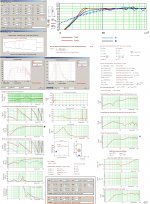
this is around 300ltrs but loses that extra bit of LF. this any better?
L - 180cm
Zdriver - 90cm
Zport - 167.5cm
So - 500cm2
Sl - 3000cm2
port - 50x12.5cm
port length - 15cm
L - 180cm
Zdriver - 90cm
Zport - 167.5cm
So - 500cm2
Sl - 3000cm2
port - 50x12.5cm
port length - 15cm
An externally hosted image should be here but it was not working when we last tested it.
So you've turned it in to a ML-TQWT now, response looks good. Anything that can do a solid 40Hz and f10 in the low 30ies should have a nice and full sound. Does excursion look reasonable at the kind of SPL you expect? In any case, it's probably better than in 500L.
How large of a room will these be used in if you don't mind me asking?
IG
How large of a room will these be used in if you don't mind me asking?
IG
Last edited:
FWIW, the way I figure such alignments, ~439 L net is the minimum for a maximally flat alignment, so you can’t shrink it much without rolling off the bass, which considering its size usually necessitates a near/at wall or corner placement, ergo it seems a reasonable trade-off if room space is at a premium.
Try ~193 L/35 Hz Fb, 142.25 cm i.d. long, driver down 49.5 cm.
GM
Try ~193 L/35 Hz Fb, 142.25 cm i.d. long, driver down 49.5 cm.
GM
Last edited:
So you've turned it in to a ML-TQWT now, response looks good. Anything that can do a solid 40Hz and f10 in the low 30ies should have a nice and full sound. Does excursion look reasonable at the kind of SPL you expect? In any case, it's probably better than in 500L.
How large of a room will these be used in if you don't mind me asking?
IG
Room isnt massive in terms of floor area, it is however 2 stories high which really sucks the life out of small drivers. I heard some tannoy Westminster's in a fairly small room and loved them, then heard some altec 604s and decided a big coax is the full range drivers I've spent so much money and time looking for
this is 280 ltrs with a manageable footprint of 42x44cm (work in progress)
what happens when the rear of the driver starts to 'block' part of the line as it does here? is it going to make an audible difference to things?
what happens when the rear of the driver starts to 'block' part of the line as it does here? is it going to make an audible difference to things?
An externally hosted image should be here but it was not working when we last tested it.
That's a DCR
Right, IG 81 ?
")
http://www.diyaudio.com/forums/full-range/236541-tb-w4-1320sif-double-bass-reflex.html
Right, IG 81 ?
http://www.diyaudio.com/forums/full-range/236541-tb-w4-1320sif-double-bass-reflex.html
That's a DCR
Right, IG 81 ?
http://www.diyaudio.com/forums/full-range/236541-tb-w4-1320sif-double-bass-reflex.html
Yes, it is.
IG
this is 280 ltrs with a manageable footprint of 42x44cm (work in progress)
what happens when the rear of the driver starts to 'block' part of the line as it does here? is it going to make an audible difference to things?
An externally hosted image should be here but it was not working when we last tested it.
Hi gafhenderson,
The procedure to simulate a FR that is ...plausible... for a Speaker like in Post#8 is IMO to make at least two different Simulations: One with the Terminus placed 'Low' and one when placed 'High':
That is: By using the System information for the Circular Driver Source from the 'System in Room Calculation graph's' and summed with the Port Response twice, i.e. Port Response #1-6dB at location Low + Port Response #2-6dB at location High.
Only the Floor = 2 x PI should be activated if to resemble a Plot that may be comparable with the MJK Far field Plot.
This processing must take place outside(below the last of MJK:s Program-lines) the MJK programs, so relabeling of all variable Names is necessary in order to avoid the possibility to mix up with MJK:s label scheme.
b
PS: Your posted Sketch-Up picture show an internal Port that is blocked by the Driver Magnet: This won't work well if not taken into consideration(Severe audible difference is expected).
Submitting two
 Pictures reflecting another view of using this Driver.
Attachments
Hi gafhenderson,
The procedure to simulate a FR that is ...plausible... for a Speaker like in Post#8 is IMO to make at least two different Simulations: One with the Terminus placed 'Low' and one when placed 'High':
That is: By using the System information for the Circular Driver Source from the 'System in Room Calculation graph's' and summed with the Port Response twice, i.e. Port Response #1-6dB at location Low + Port Response #2-6dB at location High.
Only the Floor = 2 x PI should be activated if to resemble a Plot that may be comparable with the MJK Far field Plot.
This processing must take place outside(below the last of MJK:s Program-lines) the MJK programs, so relabeling of all variable Names is necessary in order to avoid the possibility to mix up with MJK:s label scheme.
b
PS: Your posted Sketch-Up picture show an internal Port that is blocked by the Driver Magnet: This won't work well if not taken into consideration(Severe audible difference is expected).
Submitting two
wonderfully detailed reply as always B.
I shall dedicate some time to reviewing the attachments and then draw up some plans.
thanks for spotting the VAS issue, I had stripped those from the datasheet the OEM provided and the compression on the jpeg made it hard to see.
- Status
- This old topic is closed. If you want to reopen this topic, contact a moderator using the "Report Post" button.
- Home
- Loudspeakers
- Full Range
- help/tips to reduce footprint/volume of ML-TL?