For a high Qt one it could, but need specs to check...........
GM
Here are the parameters
SD=532 cm2
fs=44.4 Hz - measured, factory is 47 Hz
Mms=34 g
Qms=6.00 - measured, factory is 6.69
Qes=0.635 - measured, factory is 0.51
Re=5.64 ohm - measured, factory is 5.57 ohm
Le=0.982 mH - measured, factory is 1.01 mH
Vas=161 liters
xmax = 3.5 mm
I should add that the Sd, mms, xmax, and Vas were taken from the manufacturer specs and I expect the Vas may not be accurate if the Qms and Qes varied from the spec.
I did not do the measurements - provided with the drivers.
Last edited:
Here are the parameters
SD=532 cm2
fs=44.4 Hz - measured, factory is 47 Hz
Mms=34 g
Qms=6.00 - measured, factory is 6.69
Qes=0.635 - measured, factory is 0.51
Re=5.64 ohm - measured, factory is 5.57 ohm
Le=0.982 mH - measured, factory is 1.01 mH
Vas=161 liters
xmax = 3.5 mm
I should add that the Sd, mms, xmax, and Vas were taken from the manufacturer specs and I expect the Vas may not be accurate if the Qms and Qes varied from the spec.
I did not do the measurements - provided with the drivers.
Hi xrk971,
Here is two attempts using your Driver targeting flat FR:
b
")
Attachments
Last edited:
Bjorno,
Thanks for the simulation. If I am reading your Hornresp input page correctly, this says that you suggest a 700 square inch CSA (or 22.5 in wide x 31 in deep) x 43 in long TL with a 9.3 in dia hole in 18 mm (3/4 in) thick plywood as the vent? This makes for a shorter box but the CSA is kind of big and the location of the driver is only 21 in off the floor - not close enough to ear level. But the volume is the same as I have and it does show that you are getting a flat bass response down to 28 or 29 Hz. I am not sure how to interpret your second sim - the one shown in the Mathcad sheet.
Regards,
X
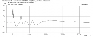
Btw, here is the freq response (again), impedance, cone excursion, and impulse response for my 60 in MLTL.
Thanks for the simulation. If I am reading your Hornresp input page correctly, this says that you suggest a 700 square inch CSA (or 22.5 in wide x 31 in deep) x 43 in long TL with a 9.3 in dia hole in 18 mm (3/4 in) thick plywood as the vent? This makes for a shorter box but the CSA is kind of big and the location of the driver is only 21 in off the floor - not close enough to ear level. But the volume is the same as I have and it does show that you are getting a flat bass response down to 28 or 29 Hz. I am not sure how to interpret your second sim - the one shown in the Mathcad sheet.
Regards,
X
Btw, here is the freq response (again), impedance, cone excursion, and impulse response for my 60 in MLTL.
Attachments
Last edited:
Thank you, GM. Confirms my suspicion of a need to use a refrigerator sized box.
But hey, the deep bass is really going to be good with a 95 to 97 dB efficiency.
One other question. With the Qts being higher, is this a good candidate for an open baffle? A CD horn in a 12 in coax in an open baffle is something I don't recall ever coming across before.
But hey, the deep bass is really going to be good with a 95 to 97 dB efficiency.
One other question. With the Qts being higher, is this a good candidate for an open baffle? A CD horn in a 12 in coax in an open baffle is something I don't recall ever coming across before.
Last edited:
Sorry guys, I just realized I had a typo on the params I provided earlier. Also there are two drivers and they differ slightly so I averaged them out. How do you get WinISD to provide the BL and Vas based on the parameters I provided?
Here are the new averaged T/S params.
Thanks,
X
SD=532.4cm2
fs=46.1Hz
Mms=34g
Qms=5.258
Qes=0.695
Re=5.55ohm
Le=0.979mH
Here are the new averaged T/S params.
Thanks,
X
SD=532.4cm2
fs=46.1Hz
Mms=34g
Qms=5.258
Qes=0.695
Re=5.55ohm
Le=0.979mH
![Eminence Beta 12CX measured [early, higher Qt].gif](/community/data/attachments/347/347942-406ec22cfe15c78d4c3b10382f017ebc.jpg)
MLTL for TangBand W4-1320-JS
XRK,
Used the accidental method to derive this design. I think you helped me before with the same driver earlier. Lost those plans and am attempting to use the method on my own. The gray areas for me are adjusting the box volume and length. I found another calculator from the Madisound site to help. Using it and Win ISD here's what I came up with. Let me know what you think.
Thanks
JH
Attachments
Jhutka,
Neat design! I will look at it more carefully later when I have time but it should work if you follow the methodology. Regarding front or rear port: more of a preference and how you plan to place it. If it is near a back wall, the rear firing will enhance the bass. If far from wall it won't make much difference other than have less HF leakage through the port to sound cleaner. If you really wanted a front firing port, make it tunnel underneath the front chamber. As that makes it longer adjust the height of the port accordingly to get same tuning. It is iterative in WinISD.
X
I'm go with something like this for TB-1320SJ:
L=66cm
driver offset ~1/3 @ 22cm
csa= 8.7cm x 14cm (~120cm^2)
Vb~8L
vent= 1.5" diameter / 1.625" long (tweak to get Fb~70Hz)
Fb~70Hz
~36g of polyfill in the top third of the line, IOW, above the driver
Qm=1.29 is an exceptionally low value, this could be a candidate for current drive in a well-damped old-school TL.
The above is hardly a floorstander, but that's what you get with a high-ish Fs, medium-low Qt driver.
If far from wall it won't make much difference other than have less HF leakage through the port to sound cleaner.
When properly designed, damped, one of the perks of a MLTL Vs a BR is the lack of audible vent pipe harmonics from the vent, so except for phase delay differences between the vent and listener, there shouldn't be any so called 'leakage' out of it.
FWIW, when I do a design where the vent winds up on the rear, I typically just bottom fire it. Problem solved.
GM
Qm=1.29 is an exceptionally low value
Yeah, a low Qm 'screams' horn driver to me.
GM
Jhutka,
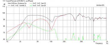
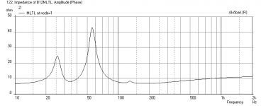
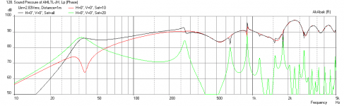
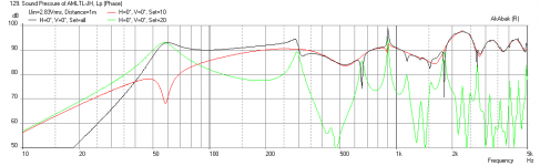
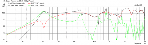
I ran a sim of your AMLTL design in Akabak and this may be a case where it does not seem to provide the correct vent dimensions. Your TL length is on the longer side and this may be pulling the tuning lower than usual. The 1 cm tall vent you have is too small and it will have an fb of around 39 Hz, which is way too deep for this driver and as a result the bass amplitude will be very low and not balanced. If you leave it rear firing, increase the vent height from 1 cm to 3 cm and that should balance it out. Or have it down-firing on legs. Alternatively, you can make a 11.65 cm long tunnel to feed it from the back to the front and in this case make the vent 3.5 cm high. This will give much better balance between bass and highs. The dips you see are from floor bounce cancellation and reflections, so final response will be placement dependent.
Here is the simulation of your design with the 1 cm tall vent with speaker placed near a back wall:
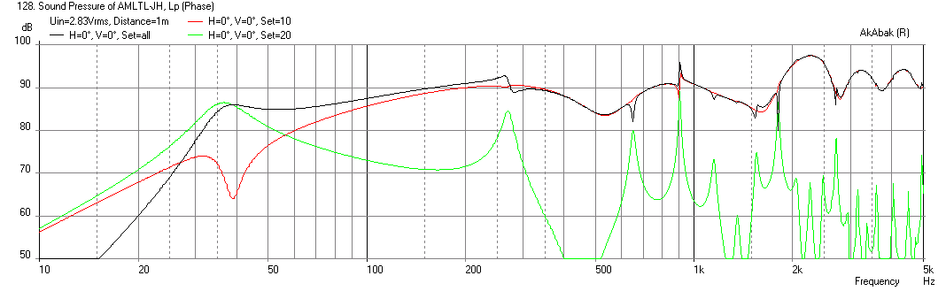
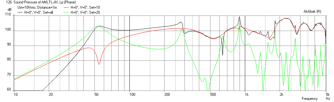
Here it is with a 3 cm tall vent:

Here it is with a 3.5 cm tall x 11.65 cm long vent and front firing:
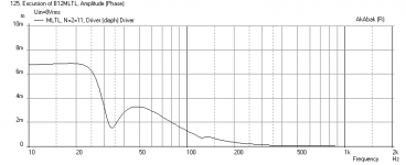
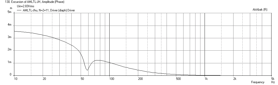
And here is the cone displacement, I think xmax happens at 7 volts so this is good for max SPL of 100 dB.
I think it can sound really nice and get decent bass extension. Just be careful with low frequency content below 40 Hz. If you place near a back wall you will not need any BSC even.
I ran a sim of your AMLTL design in Akabak and this may be a case where it does not seem to provide the correct vent dimensions. Your TL length is on the longer side and this may be pulling the tuning lower than usual. The 1 cm tall vent you have is too small and it will have an fb of around 39 Hz, which is way too deep for this driver and as a result the bass amplitude will be very low and not balanced. If you leave it rear firing, increase the vent height from 1 cm to 3 cm and that should balance it out. Or have it down-firing on legs. Alternatively, you can make a 11.65 cm long tunnel to feed it from the back to the front and in this case make the vent 3.5 cm high. This will give much better balance between bass and highs. The dips you see are from floor bounce cancellation and reflections, so final response will be placement dependent.
Here is the simulation of your design with the 1 cm tall vent with speaker placed near a back wall:
Here it is with a 3 cm tall vent:
Here it is with a 3.5 cm tall x 11.65 cm long vent and front firing:
And here is the cone displacement, I think xmax happens at 7 volts so this is good for max SPL of 100 dB.
I think it can sound really nice and get decent bass extension. Just be careful with low frequency content below 40 Hz. If you place near a back wall you will not need any BSC even.
Attachments

So i've been following this (and other MLTL) threads for a while now - have experimented with a few TL designs (TABAQ, TABAQ-Box and my own ML-TQWT) with surprisingly good results. However I've been curious about the 'accidental MLTL' process, and am curious what sort of results are possible in retrofitting a TL to an existing bass reflex speaker.
What I have in mind is a modification where the existing port becomes the ML part, and a set of internal divisions shape the folded transmission line. I'm currently in the process of finishing off a pair of modified Overnight Sensations - I've made some curved boxes with a larger volume and changed the port tuning slightly, the front baffle width is the same, but it is taller. Now I'm considering adding in some internal partitions to turn it into a ML-TL, but don't know whether it will be worthwhile, or what the best dimensions for the TL would be.
I have MJK's worksheets, so will start experimenting, probably with a tapered ML-TL. Anybody have any insights as to good starting points?
You are on the right track with wanting to convert a BR box into a MLTL. The tricky thing will be to get enough length and cross sectional area at the same time. A good rule of thumb is to have the cross sectional area about 3x to 4x the driver Sd so it doesn't sound congested. Try to get at least 30in length fold for a 3 to 4in driver and 40in to 48in for a 5 to 6in driver, and up to 60in if you can get it for an 8in driver. Try to put driver between 20% to 33% from closed end. If you have worksheets you can model it very accurately. The AMLTL technique is for those without sims.
- Home
- Loudspeakers
- Full Range
- Accidental MLTL Technique