They sound very good. As usual, those drivers are expensive locally but can get a better deal from Hong Kong.
Is there any way to get better bass from the TC9FD in this design, or is it limited by the high fs? The foamcore sheets I have are 841mm long, so it would be easier for me to increase the cross-sectional area rather than length but then I go against the recommended 4x Sd.
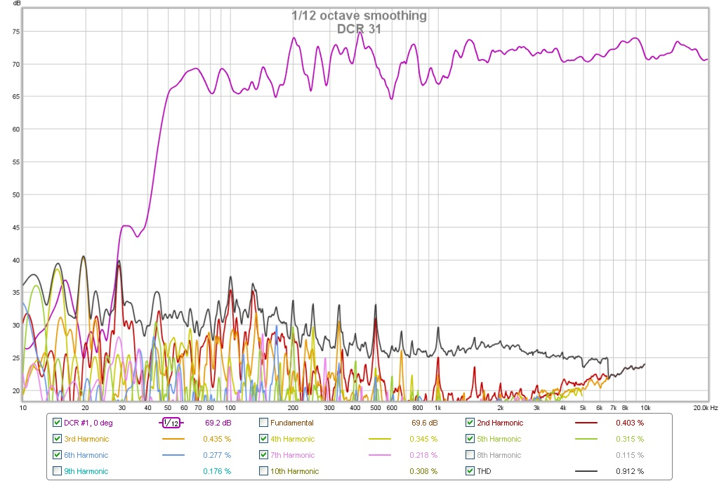
The deepest clearest bass with TC9FD is the DCR design I made. It's 50Hz and fairly low distortion at moderate volumes.
http://www.diyaudio.com/forums/full-range/252627-viva-la-vifa-curvy-cabinet-dcr-tc9fd.html
http://www.diyaudio.com/forums/full-range/252627-viva-la-vifa-curvy-cabinet-dcr-tc9fd.html
With a Fs of 125 Hz, it is hard to get sufficient bass.
My Micro TABAQ with 2" Tang Band Fs 160 Hz delivers down to 70 Hz at low levels with a little help from the EQ on my PC.
My Micro TABAQ with 2" Tang Band Fs 160 Hz delivers down to 70 Hz at low levels with a little help from the EQ on my PC.
Maybe a DCR is the way to go. If I did it in a columnar format, it could be free standing with a small footprint. Folding each speaker out of an A1 sheet of foamcore gives 142 mm x 142 mm x 841 mm (5.81" x 5.81" x 33.11") internal and volume of 16.3 L for both chambers combined.
You can do DCR in curved folded column like the Tabaq I made but with partitions for two chambers for DCR. The curved structure is very rigid with a few braces. Use 1 sheet if 30in tall x 20in wide foam core to roll into one speaker. Add a few more inches height with a rolled around base.
Anyone tried exotic drivers in an mltl? Was thinking along the lines of Accuton and scan illuminators
The thing about port lengths.... Stuff I've noticed.
I've been doing some playing around with Leonard software's Transmission Line program for a while now. I've just been working my way through the 1st post while modelling a Dayton ND105-8 in WinISD and TL.
In the TL software, if you place the port in the exact centre of the line, then the WinISD calculated port length seems about right. However, as you move the port further to the right, towards the end of the line, the tuning of the box drops quite markedly. To obtain the same tuning frequency near the end of the line requires a much shorter port. I guess because it's also starting to behave as a reduced X-section TL in addition to the port resonance.
J.
If using two drivers per side in an mltl, do you always have to cram them at the top of the cab? (Unfolded). What would happen if they were placed too far down the line, or say half way along for the second one?
Last edited:
If using two drivers per side in an mltl, do you always have to cram them at the top of the cab? (Unfolded). What would happen if they were placed too far down the line, or say half way along for the second one?
In theory you'd place them to reduce or remove harmonics in the pipe/line.
You can model driver placement vs frequency response in Leonard Audio Transmission Line software.
With an MLTL, the driver placement does tend to be further down the pipe if suppressing the 3rd harmonic to get a smoother bass response - than in a parallel full size TL, where the driver would be at 1/3 pipe length or thereabouts.
I'm pretty sure there are all sorts of issues when running multiple drivers that I have the vaguest inklings of but am certainly no expert.
J.
From what I have seen in sims, placement anywhere from 0.20x to 0.5x from closed end will yield an Ok response. But to best suppress the undesirable harmonics one needs to use a model and simulate the response for optimal results. Since the point of this thread is to NOT use a model, the suggested 0.33x placement will pretty much give you the best results. When using two drivers the mid point between them acts as the centroid of their response as a first approximation. You can vary by a few inches up or down and it's not a big deal.
From what I have seen in sims, placement anywhere from 0.20x to 0.5x from closed end will yield an Ok response. But to best suppress the undesirable harmonics one needs to use a model and simulate the response for optimal results. Since the point of this thread is to NOT use a model, the suggested 0.33x placement will pretty much give you the best results. When using two drivers the mid point between them acts as the centroid of their response as a first approximation. You can vary by a few inches up or down and it's not a big deal.
Ah, I hadn't meant to derail your topic, apologies.
More a case of using the tool to demonstrate harmonics and harmonic suppression as it seemed pertinent to the question.
J.
Since the point of this thread is to NOT use a model, the suggested 0.33x placement will pretty much give you the best results.
FWIW, there's an optimum for each alignment, but must be calculated from an accurate 3D model; otherwise, based on MJK's Classic TL design doc and using his software: his offsets, while a bit different in some cases than my 3D ones can be ameliorated with minor differences in stuffing density [ditto in Hornresp], hence in many cases probably not audible except possibly in an un-damped cab, so recommend using his as 'close enough' unless the flare is steeper than his charts go and even then don't shift much according to his software, so can still be dealt with by adjusting stuffing density and/or distribution along the line, so still recommend these as a de facto 'rule-of-thumb' whether simmed or not.
GM
Last edited:
Ah, I hadn't meant to derail your topic, apologies.
More a case of using the tool to demonstrate harmonics and harmonic suppression as it seemed pertinent to the question.
J.
No worries - did not think you were derailing it at all. Just the fact that an AMLTL is meant to allow the casual user without simulation tools the ability to build a half decent TL speaker.
Q would the Satori MW13P-4 work in a compact MLTL? QTS is too low for standard TL
Had these drivers sitting around for far too long..
Had these drivers sitting around for far too long..
MLTL works well with mid-value Qts. Low Qts can work with a tapered (small exit) TL that is heavily damped. Response looks a lot like a bass reflex but without the bass reflex boominess or poor group delay. I may have actually ran a sim of the MW13 as a TL already somewhere. Good for 45Hz if I recall.
Hi
Tuning of the enclosure depends on the Qts:
Just a general tip
Above 0.35: Below Fs
Below 0.35: Above Fs
Hi
Bjørn
Tuning of the enclosure depends on the Qts:
Just a general tip
Above 0.35: Below Fs
Below 0.35: Above Fs
Hi
Bjørn
I've been considering a build for quite a while now, but am still not entirely sure how its going to unfold. Inspired by this build by xrk971, but with a TC9FD, and possibly a tweeter. However, instead of going sealed and LT, I'm thinking floorstanding TL, but still undecided...
Modelling this (in Leonard Audio's Transmission Line software) makes it relatively easy to mess around with the parameters and see what happens - and what I've noticed is that when I start with WinISD suggested sizes for a bass reflex and model it as a MLTL, it seems to have the smoothest response when the woofer is mounted in the middle of the chamber, with the tradeoff of a deeper notch.
Making the box longer (half the cross section, double the length) brings the resonances lower - but does offer better extension. Stuffing the box (low density) AND the port (high density) flattens these resonances out almost completely. Was surprised about the center position of the woofer though, I thought positioning at a third was best. Also good to see the effect of the resonances for the same size enclosure but different internal construction...
Time to do some testing!
Attachments

- Home
- Loudspeakers
- Full Range
- Accidental MLTL Technique