That was awfully nice of you to run a sim of the hand sketched box for the OP. The design looks really good. I don't know if Gost22 realizes how much we are going out of our way to provide suggestions and actual dimensions because it looks like he may just go with another design or driver.
Mr. krk971, please define exactly which picture (drawing) referred to in this box your exposure panekako all understand that, since I was little English.
thanks for your help!
Gost22,
The drawing you provided on post number 12, has corresponding dimensions on post number 14 by Scottmoose. Those two posts contain all the info in dimensions needed to construct the horn/transmission line you seek including full simulations of the response.
In this thread are also several other designs with dimensions (a BIB from myself, and one by GM)f if you take the time to read.
Cabinet for BG-20
Hi xrk971!
Is it should look like this box with these dimensions or something needs to change?
What is the value of X and Y?
Or box should look like the second picture (Figure 1)
thank you!
Hi xrk971!
Is it should look like this box with these dimensions or something needs to change?
What is the value of X and Y?
Or box should look like the second picture (Figure 1)
thank you!
Attachments
Last edited:
Gost22,
I will try to assist you one last time. Like I said, all the information you need is in post 14 and it refers to the hand drawn sketch you posted in post number 12. The pdf's you attached can't be opened - all I see is black. It doesn't matter we are talking about picture you provided. I guess you want a drawing labeled with dimensions as you cannot transcribe the words in post 14 to the corresponding dimension in post 12.
Here is what Scottmoose provided in post 14:
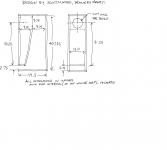
" -Cabinet height = 40.25in -Width = 12in -Total internal cabinet depth = 19.5in -Throat depth = 4in -Taper ratio = 1:4 -Height of vent = 2.75in -Zd (distance of the centre of the drive unit from the throat) 31.125in -Top of internal baffle centred equidistant from the internal top, back and front -Line the front and top of the box around the fold with damping material. This should be continued for 10in down the back of the enclosure. Adjust to requirements from there. A removable back to the cabinet would be useful to allow easy stuffing adjustment."
Translated to easy dimensions: x, y, z coordinates with x for horizontal dimension, y for vertical dimension, and z into the page dimension (width of cabinet viewed from front).
1. Make cabinet 40.125 inches tall in y dimension (height)
2. Make cabinet 12.0 inches in z dimension (width)
3. Make cabinet 19.5 inches in x dimension (depth)
4. Make the vent gap at bottom (terminus or horn output) 2.75 in in the y direction
5. Make the vent length in the x direction 4.0 inches
6. Make the internal divider panel equidistant from the front, back, and top, meaning locate it 9.75 in from the front in x direction, 9.75 in from top in y direction, and 9.75 in from back in the x direction.
7. Attach the bottom of the internal divider to the end of the 4 in long vent piece at the bottom.
8. Make a round hole or cut out for the BG20 driver at a location 31.25 inches in the y direction from the top edge of the vent.
Those are all the dimensions you need. I saw you asked someone in the photo gallery what the dimensions of their BG20 cabinet was. I would not be surprised if it was very similar to this.
We are all trying to help you, and spending a lot of time at it too. Please try to read this carefully and make an effort to write the above dimensions down next to your picture (provided sketch below). If you continue to ask for assistance but do not make an effort to use or understand what is provided to you, it is a waste of everyone's time.
Regards,
xrk971
I will try to assist you one last time. Like I said, all the information you need is in post 14 and it refers to the hand drawn sketch you posted in post number 12. The pdf's you attached can't be opened - all I see is black. It doesn't matter we are talking about picture you provided. I guess you want a drawing labeled with dimensions as you cannot transcribe the words in post 14 to the corresponding dimension in post 12.
Here is what Scottmoose provided in post 14:
" -Cabinet height = 40.25in -Width = 12in -Total internal cabinet depth = 19.5in -Throat depth = 4in -Taper ratio = 1:4 -Height of vent = 2.75in -Zd (distance of the centre of the drive unit from the throat) 31.125in -Top of internal baffle centred equidistant from the internal top, back and front -Line the front and top of the box around the fold with damping material. This should be continued for 10in down the back of the enclosure. Adjust to requirements from there. A removable back to the cabinet would be useful to allow easy stuffing adjustment."
Translated to easy dimensions: x, y, z coordinates with x for horizontal dimension, y for vertical dimension, and z into the page dimension (width of cabinet viewed from front).
1. Make cabinet 40.125 inches tall in y dimension (height)
2. Make cabinet 12.0 inches in z dimension (width)
3. Make cabinet 19.5 inches in x dimension (depth)
4. Make the vent gap at bottom (terminus or horn output) 2.75 in in the y direction
5. Make the vent length in the x direction 4.0 inches
6. Make the internal divider panel equidistant from the front, back, and top, meaning locate it 9.75 in from the front in x direction, 9.75 in from top in y direction, and 9.75 in from back in the x direction.
7. Attach the bottom of the internal divider to the end of the 4 in long vent piece at the bottom.
8. Make a round hole or cut out for the BG20 driver at a location 31.25 inches in the y direction from the top edge of the vent.
Those are all the dimensions you need. I saw you asked someone in the photo gallery what the dimensions of their BG20 cabinet was. I would not be surprised if it was very similar to this.
We are all trying to help you, and spending a lot of time at it too. Please try to read this carefully and make an effort to write the above dimensions down next to your picture (provided sketch below). If you continue to ask for assistance but do not make an effort to use or understand what is provided to you, it is a waste of everyone's time.
Regards,
xrk971
Attachments
Last edited:
Hi,
Definitely happy end. The following procedure for making boxes and making the cross-over to align the frequency response.
See ultimate drawing boxes.
Cheers!
Gost,
The drawing looks good. I hope you build it - we are looking forward to the photos and first impressions of sound.
Good luck!
Interesting! This cab has less net Vb, but a larger footprint due to being shorter than my 60" MLTL, so mine has a marginally better LF response, yet in theory the Voigt pipe doesn't have as good an HF response, hence transient response due to being an expanding MLTL with a larger, longer vent.
Once again proving that in the majority of cases a simple MLTL is the best overall alignment.
Both sims are stuffed identically and latest revised driver specs used.
Voight pipe on the left:
GM
Once again proving that in the majority of cases a simple MLTL is the best overall alignment.
Both sims are stuffed identically and latest revised driver specs used.
Voight pipe on the left:
GM
Attachments
![Bg20 Voigt pipe [Gost22].gif](/community/data/attachments/301/301101-8d24b84b0ecc8c4051fff76907ddda83.jpg)
![Visaton BG20 35 Hz MLTL [pipe horn damping].gif](/community/data/attachments/301/301103-e0eb597bcbe69d685db20e4e35b7c687.jpg)
Hi GM!Interesting! This cab has less net Vb, but a larger footprint due to being shorter than my 60" MLTL, so mine has a marginally better LF response, yet in theory the Voigt pipe doesn't have as good an HF response, hence transient response due to being an expanding MLTL with a larger, longer vent.
Once again proving that in the majority of cases a simple MLTL is the best overall alignment.
Both sims are stuffed identically and latest revised driver specs used.
Voight pipe on the left:
GM
G-GM does not suggest what the two of you and get you listed (I understand) ML TL or TQWT box?
thank you!
...Once again proving that in the majority of cases a simple MLTL is the best overall alignment.
+1. Personally I'd go with an MLTL pretty much every time it's a viable option over an ML horn / Voigt. Since he asked for one of the latter (amongst many other things
) I gave him one, but simple works for me too.
Last edited:
Hi GM!
G-GM does not suggest what the two of you and get you listed (I understand) ML TL or TQWT box?
thank you!
You are welcome, though sorry, I do not understand what you are asking.
GM
Understood, I just wanted to point it out for any less well informed folks that are or may in the future browse this thread.Since he asked for one of the latter (amongst many other things
GM
Good point.
For the other, I'm guessing he was asking which of the two graphs in your post was which. My suspicion is that he doesn't speak any English at all and is going through some kind of on-line translation package, so the majority of what we're saying is lost, even some of the simple stuff like that. Let's see if this works:
'TQWT' (Voigt pipe / ML horn) on the left.
MLTL on the right.
Hmm, I see I spelled Voigt right once, wrong once.
Anyway, out of curiosity, I used Google to translate it into Spanish, then back again and it did better than I expected, but still pretty confusing even though I already know what it all means.
GM
Interesting! This car has less Vb net, but a larger footprint due to be shorter than my 60 "MLTL, so mine has a slightly better LF response, however, the theory of Voigt pipe is not as well high frequency response, the response must therefore be a MLTL transient expansion with a larger, longer ventilation.
Proving once again that, in most cases a single MLTL is the best overall alignment.
Both sims are populated identically and used last revised controller specifications.
Voight left tube:
GM
You are welcome, though sorry, I do not understand what you are asking.
GM
Hi GM!
I was wondering which is the better option boxes for BG-20 ML-TL or ML-TQWT, that which gives better sound?
Otherwise you all understand ...
I stand poor with the English , so I'm going to translate google.
Cheers!

I do not know, I only know that mathematically the MLTL is the better performing design [alignment] overall.
As 'picowallspeaker' suggested, the only way to know for sure if the sonic differences are enough to be audible as well as 'better', you would have to make one of each type and compare them
Good luck with whichever one you build and please come back and let us know how they perform.
GM
As 'picowallspeaker' suggested, the only way to know for sure if the sonic differences are enough to be audible as well as 'better', you would have to make one of each type and compare them
Good luck with whichever one you build and please come back and let us know how they perform.
GM
- Status
- This old topic is closed. If you want to reopen this topic, contact a moderator using the "Report Post" button.
- Home
- Loudspeakers
- Full Range
- TL-box for BG20 Visaton