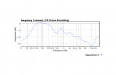
|
|||||||
| Home | Forums | Rules | Articles | Store | Gallery | Blogs | Register | Donations | FAQ | Calendar | Search | Today's Posts | Mark Forums Read | Search |
|
Please consider donating to help us continue to serve you.
Ads on/off / Custom Title / More PMs / More album space / Advanced printing & mass image saving |
|
![]() |
|
|
Thread Tools | Search this Thread |
|
|
#61 |
|
diyAudio Member
Join Date: Nov 2009
|
Do you have waterfall plots for the lower frequencies?
These might help figure out if the lower frequencies you are measuring are dominated by room modes. |
|
|
|
#62 |
|
diyAudio Member
Join Date: Apr 2003
Location: Stockholm
|
The plan is to do further measurements
1. No damping material at all! As a horror reference! 2. Damping in chamber and IHR and nothing in P2 and P3, regarding P1 I am on the fence. This would represent the classical damping scheme 3. As 2 but with the IHR filled with something solid like a plastic bag filled with sand or rice. This would represent the classical damping scheme wih no IHR If I focus on the impedance peak at 35 Hz and dip at 45 Hz; Adding damping in the chamber does nothing +IHR reduce the peak a 2 Ohm +P1 reduce the peak 3 ohm +P2 reduce the peak from a 7 ohm peak to a 1 ohm hump and also reduce the dip at 45 Hz +P3 and the dip is gone and the peak is just a shoulder of less slope 30-40 Hz. If I do water fall plots in the bass it will tell me what I know, the room is bad. I wished I had access to a really large room with a good corner and measure the total output at 3 m or so |
|
|
|
#63 | |
|
diyAudio Member
Join Date: Nov 2009
|
Quote:
When you refer to the -6db points, you need to bear in mind that these are usually calculated relative to the driver's nominal SPL, and not to the horn's maximum level. As you can see in one of your measurements (horn in corner, mic at 1m), if we consider the driver's nominal SPL to be around the 67.5db mark on the graph (as shown in the 500hz-2khz region where the horn contribution is nill) the horn is a relatively high gain design raising the SPL around 5db above nominal in its bandwidth (40-200hz). Now take the levels at 65 and 150hz on the graph, go 5db lower, and look at what frequencies get intersected. Pretty close to 40 and 200hz ![]() edit: try smoothing your graphs, say 1/12 or 1/6 octave smoothing Last edited by hajj; 24th January 2013 at 09:02 AM. |
|
|
|
|
#64 |
|
diyAudio Member
Join Date: Apr 2003
Location: Stockholm
|
I have made som more measurements of the pipe output, now I had good use of the small tripod that was included!
![]() Omnimic does some kind of automatic level adjustments in graphs so I am not so sure about output diffrences. My focus is the balance between shelf at 40-60 Hz and the peaks at 95 and 190 Hz. The top black trace is with damping material in only the chamber and IHR Blue with P1 Green with P1 and P2 added Yellow with P1, P2 and P3 added My interpretation was that the pipe stuffing do reduce the 190 Hz peak a lot but at the expense of bass shelf output. ![]() Here I have no damping in P2 and P3 and I have 42 g in the chamber. I have some of the shelf back and the 190 Hz peak is decent. I still wanted to get a better shelf and get rid of that pesky 190 Hz. I removed the damping material in P1 and just to try it out I filled the IHR with a bag of rice. ![]() The shelf is good down to 40 Hz, the 190 Hz peak is reduced by 7 db! I still have that 95 Hz 8 dB hump. Perhaps if I retune the IHR to 95 Hz and have some resisitive damping to keep the Q low I could reduce the output 6 db between 70 and 120 Hz? |
|
|
|
#65 |
|
diyAudio Member
Join Date: Oct 2012
Location: Virginia
|
Dr Boar,
What a terrific set of measurements. Have you tried adding a bag of rice in the driver chamber? Nice work! |
|
|
|
#66 |
|
diyAudio Member
Join Date: Apr 2003
Location: Stockholm
|
The rice was used to fill the IHR to accoustically close it. Reducing the volume of the driver chamber is not something I have tried.
I have used a online calculator mh-audio.nl - Acoustic The original IHR has very wide band with 105-405 Hz, if I try to lower the resonance from 255 Hz to around 95 Hz by using a smaller and longer port the band with shrink to much less one 25mm hole in 33 mm thick board result in 89 Hz and 0.43 Hz bandwith two holes 25mm diameter gives 116 Hz and 1.5 Hz... Regarding T/S paremeters look at page 2 post 18, I am using the driver with SN 404 |
|
|
|
#67 |
|
diyAudio Member
Join Date: Apr 2003
Location: Stockholm
|
Now I have blocked the IHR and drilled two 25 mm diameter holes in two layers of 11 mm OSB so the tuning frequencys are 100 Hz and 128 Hz with one and two holes open respectively. Here I have the speaker chamber even more densly stuffed 63 grams!
![]() The black curve is closed vents and it is quite similar to the rice bag in previous measurements with less damping, the main difference is less of a peak at 190 Hz. The brown and red curve are two measurements with one hole open (tuning 100 Hz) taken before and after the two hole measurement. It does nothing for the 90 Hz peak but lowers the 100-160 Hz range by 5 dB or so. The blue is with both vents open and a calculated tuning of 128 Hz and it takes out 5-10 dB from 130 to 210 Hz. I think it looks like the best combination so far, but I would rather have reduced that 90 Hz hump than the one around 160 Hz. I will search my house for tubes of 25mm OD with such an item I could tune all the way down to 60 Hz. |
|
|
|
#68 | |
|
frugal-phile(tm)
diyAudio Moderator
|
Quote:
dave
__________________
community sites t-linespeakers.org, frugal-horn.com, frugal-phile.com ........ commercial site planet10-HiFi p10-hifi forum here at diyA |
|
|
|
|
#69 |
|
diyAudio Member
Join Date: Nov 2009
|
|
|
|
|
#70 |
|
diyAudio Member
Join Date: Apr 2003
Location: Stockholm
|
Well at 15C the density has decreased to 0.999 and at 45C it is still 0.99 so for a kitchen scale that is good enogh. I would need a calibrated Voll pipette to get the error of added volume down into the 0.1% range, I make food in my kitchen not analytical chemistry.
I found a tube containing vitamin C that was close to 25mm I am gluing it to one of the vents I hope the latex sealant have cured by tomorrow. If I would make a new prototype I would make "manholes" or rather "handholes" to access the compartments and have most of the speaker closed. There is a lot of vibrations going on when the whole side is structurally disconnected to the rest of the enclosure. |
|
![]() |
| Thread Tools | Search this Thread |
|
|
Similar Threads
|
||||
| Thread | Thread Starter | Forum | Replies | Last Post |
| Disadvantage for place the Fostex 168e sigma into Fostex 166e BLH enclosure ? | davidshya | Full Range | 2 | 27th January 2013 09:41 PM |
| Fostex ff125wk drivers and amps and more for sale? | Cross Reference | Swap Meet | 0 | 15th December 2012 08:31 PM |
| Mileva Build Using Fostex FF125WK Drivers | tomlang | Full Range | 7 | 21st November 2012 03:52 AM |
| fostex ff125wk vs markaudio alpair 7.3 (or10.2) | castorG | Full Range | 4 | 20th October 2012 07:12 PM |
| taming harshness of fostex FF125WK | hajj | Full Range | 133 | 15th October 2012 04:34 PM |
| New To Site? | Need Help? |