Dr Why,
OMG - That’s a monster! Truly awesome size. You must have a very understanding significant other. Good luck in the build and looking forward to seeing the most massive Cornus ever. That’s 36 square feet of baffle in case anyone is wondering. Where do you even find 1.8mx1.8mx25mm plywood?

OMG - That’s a monster! Truly awesome size. You must have a very understanding significant other. Good luck in the build and looking forward to seeing the most massive Cornus ever. That’s 36 square feet of baffle in case anyone is wondering. Where do you even find 1.8mx1.8mx25mm plywood?
Hi
@xrk971
It's not Plywood - the Plates are of 25mm Chipboard (in Germany we say "Mitteldichte Faser" or MDF) and is made of very fine Wood Flour. Sorry, i don't know the American Name for it...
Each Plate is 73 kg weight.
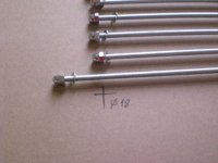
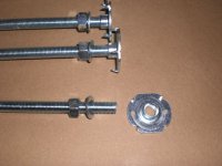
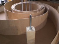
The Four Horn Contour(s) are of 10 mm bendable Plywood, glued and pressed between the 25mm MDF Plates with 8 threaded Rods 8mm and 4 threaded Rods 16mm (see pic below driver with 8 Rods 8mm).
Greetings
DW
@xrk971
It's not Plywood - the Plates are of 25mm Chipboard (in Germany we say "Mitteldichte Faser" or MDF) and is made of very fine Wood Flour. Sorry, i don't know the American Name for it...
Each Plate is 73 kg weight.
The Four Horn Contour(s) are of 10 mm bendable Plywood, glued and pressed between the 25mm MDF Plates with 8 threaded Rods 8mm and 4 threaded Rods 16mm (see pic below driver with 8 Rods 8mm).
Greetings
DW
Attachments
MDF is medium density fiberboard and chipboard is actually chips of wood pressed together (less smooth) but stronger in my opinion from toughness standpoint. Even in MDF, 6ft x 6ft is hard to find as 5ft x 5ft or 4ft x 8ft are the standard sizes. Can't wait to see this thing built. Your 5.8m length horn should be good for 16Hz corner frequency. Organ music anyone?
Hi,
Yes, "medium density fiberboard" was the Name...
The only available Wood in this Size 6" is MDF and normal Fiberboard. The whole sheet of MDF is 2.80 x 2.05 Meter. I paid 322 Euro for all (Boards, cutting and delivering to my home).
Only for Interest:
Horn Lengh : 2x 4.8 m plus 2x 5.40m
Horn Throat Area: 300 cm² (Driver Diaphragm Area 370 cm²)
Horn Mouth Area 4x 1.80m x 0.3 m = 2,16 m² plus at least one Mirror Area (Wall) = 4.32m²
Sorry for all the metric Units...
My Goal is 32 Hz full Power (-3dB) for "normal" Music listening - no Home cinema or PA use.
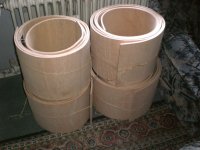
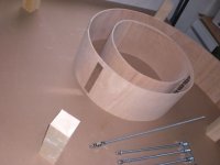
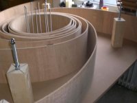
Below a Pic of the drying bendable Plywood (bended wet) :
Left the short ones (4.80m) and right the longer (5.40m)
D.W.
Yes, "medium density fiberboard" was the Name...
The only available Wood in this Size 6" is MDF and normal Fiberboard. The whole sheet of MDF is 2.80 x 2.05 Meter. I paid 322 Euro for all (Boards, cutting and delivering to my home).
Only for Interest:
Horn Lengh : 2x 4.8 m plus 2x 5.40m
Horn Throat Area: 300 cm² (Driver Diaphragm Area 370 cm²)
Horn Mouth Area 4x 1.80m x 0.3 m = 2,16 m² plus at least one Mirror Area (Wall) = 4.32m²
Sorry for all the metric Units...
My Goal is 32 Hz full Power (-3dB) for "normal" Music listening - no Home cinema or PA use.
Below a Pic of the drying bendable Plywood (bended wet) :
Left the short ones (4.80m) and right the longer (5.40m)
D.W.
Attachments
Oh, an isobaric arrangement. This is usually used to reduce the minimum chamber volume to allow a deeper bass extension in a sealed box. I’m not quite sure if you are buying anything with it in a BLH arrangement. Certainly I can simulate this in Akabak. Let me give it a shot and see what the influence of the isobaric vs a single driver is.
So for simplicity I will assume you are following a 2.5x scaled up plan of the Cornu to get 180cm x 180cm and use 30cm deep channels.
So for simplicity I will assume you are following a 2.5x scaled up plan of the Cornu to get 180cm x 180cm and use 30cm deep channels.
Hi,
Yes, you're 100% right - i scaled it up 2.5x and clipped it at 1.8 Meter due to Door Limitations. So the Horn contour is slightly different from the original Cornu.
Also i make the Snail in a smmoth, round Shape without edges like the original Cornu, because the bendable Plywood allows only 150 mm bending Radii (250mm when bended dry).
A Akabak Simulation with two Drivers sound interesting - for me, too. Thanks a lot.
D.W.

Hi,
Cheers Paul !
15 Hertz is a "nice to have" but make no sense, because the maximum possible Mouth Area (even with Mirror Areas) is way tooo small for this Frequency.
Early Calculations with Hornresp said 27 Hz fu (-3dB) with one Mirror Area (Wall mounting). Even at 27 hz this Mouth Area (4.32 m²) is too small for correct Horn function. I hope the nearby Ground, Sidewalls and Ceiling Areas add some more m²...
Btw: i've planned to add an active, special subsonic Filter (from THEL, Germany) at around 25 Hz with 5th Order (30dB/Oct) to prevent excessive Cone Excursions and to reduce Distortions.
Next Year (maybe Feb. or march) i'd start to build up the Bass Amp (Class D and 500 -1000W).
D.W.
Hi Guys,
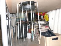
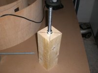
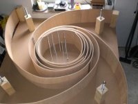
Unfortunately, I had a cold and therefore down, but today I put together quickly what belongs together: Somewhat later the horn looks like (here without cover plate) - only that the inner radii are much smaller than seen in the picture above. I think that nothing will happen this week, so it will continue next week.
D.W.
Attachments
Those channels look so close together - are you getting any flow through them? Or that will be corrected once glued down? Can you share with us the scaled plan showing the channel spacing and where things go?
You might consider using small wedges or trapezoids of wood equal to the channel gap and glue them in place at regular intervals to define channel width, and to reduce resonance/noise and distortion when playing music. Those channel walls may vibrate a lot without bracing in the plane parallel to front/back panels.
Nice progress though.
Hi,
no, this is not the final mounting position - this is just for a better understanding and overview of what the horn will look like later.
The inner radius of the chamber will be about 30cm - in the picture it is more than twice as large due to the tension of the plywoods. And logically, the channels are reinforced by spacer blocks. D.W.
- Home
- Loudspeakers
- Full Range
- Ever think of building a Cornu Spiral horn? Now you can!