xrk 20 inch speaker plan
Your work and contribution are very impressive. I plan to build a 20 inch speaker with Vifa TC9FD. Noting that you have changed the throat width, would you mind to share a print of your 20 inch plan ?? I hope to get a successfuly reproduction. Thank you in advance.
By the way I have also gone through the other 100+ pages Foam Board thread and cant find your 20 inch plan as well. I only find the original sebastian and planet10 plans.
Kambule and Ramzilla,
I am on travel this week and do not have access to the file of the photo of my plan. However, if you take a look at the photo of the completed channels, you may try to use that as a guide in drawing your plan. Post #45 in http://www.diyaudio.com/forums/full-range/223313-foam-core-board-speaker-enclosures-5.html
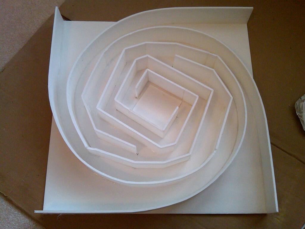
I do not have a pdf as it is a large full scale hand drawn plan - you will get a photo from top view.
If you are itching to start, this should get you going. If I were to redo this, I would increase depth to 3 in.
Regards,
Xrk971
I am on travel this week and do not have access to the file of the photo of my plan. However, if you take a look at the photo of the completed channels, you may try to use that as a guide in drawing your plan. Post #45 in http://www.diyaudio.com/forums/full-range/223313-foam-core-board-speaker-enclosures-5.html
I do not have a pdf as it is a large full scale hand drawn plan - you will get a photo from top view.
If you are itching to start, this should get you going. If I were to redo this, I would increase depth to 3 in.
Regards,
Xrk971
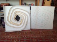
I have finally completed one of the Cornucopya horns for my Altec 405A drivers. Photos below of the build in-progress and the one finished speaker.
28” x 28” x 5” (channel depth). Using foam core for the back plate and 1/4” plywood for the baffle (which is really 3/16” thick, leaving one to ponder again about truth in advertising for wood products). To make the back plate, I spliced pieces of foam board together with paper and Mod Podge.
Initial attachment of channels with hot melt glue in the style of a caulk gun on one side, with the other side getting a line of wood glue to ensure firm attachment. Gorilla glue was applied to the edges of the channel foam boards; flipped over onto the baffle and weight applied with books until the urethane glue cured. Heavily stuffed with fiber fill behind the driver; lightly stuffed from the throat to the bifurcation in the horn.
There was room in the driver chamber for two of the driver mounting screws to be reinforced with small bits of wood on the back side, but not for the two others. So I used the old trick to strengthen the ‘threads’ in the thin wood baffle: drilled pilot holes, ran the screws in, removed them, then applied (thin, runny) super glue. Let the glue soak in & set up for a couple hours before mounting the drivers.
I didn’t bother with binding posts, just took an ice pick & put it through the back, ran the wire through, then sealed it with hot melt glue.
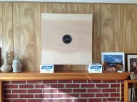
To hang the horn on a wall, I plan to use 3M’s Command Brand utility hooks. I suppose I could have glued a wood strip to the back & used regular picture hanging hardware, but this seems easier.
My wife’s comment upon seeing the horn placed on the mantle was: “That seems appropriate for this house.” (Understand that she knows it isn’t a long term placement.) On hearing the single completed horn she said, “Not Bad!” Her expectations were rather low for this foam board creation. After 41 years of marriage, she has expectations that any speaker worth listening to has considerable mass relative to its size.
I think they are somewhat anemic, probably due to Stiff Surround Syndrome (SSS). Less charitable folks might say they sound like Antique Surround Syndrome. Application of tone controls--cutting treble and boosting bass--results in a listenable, but unremarkable, sound. None the less, the sonic presentation is interesting. I will complete the second horn then decide on a further course of action.
I am debating the merits of pulling a driver from a previous build to see how it might work in this Cornucopya. Or should I just buy some new drivers? Would an FE103en work? (I am curious about this driver, as it has almost legendary status in Japan.) Been thinking I would like to sample those $12 Vifa drivers xrk favors too...
Cheers, Jim
28” x 28” x 5” (channel depth). Using foam core for the back plate and 1/4” plywood for the baffle (which is really 3/16” thick, leaving one to ponder again about truth in advertising for wood products). To make the back plate, I spliced pieces of foam board together with paper and Mod Podge.
Initial attachment of channels with hot melt glue in the style of a caulk gun on one side, with the other side getting a line of wood glue to ensure firm attachment. Gorilla glue was applied to the edges of the channel foam boards; flipped over onto the baffle and weight applied with books until the urethane glue cured. Heavily stuffed with fiber fill behind the driver; lightly stuffed from the throat to the bifurcation in the horn.
There was room in the driver chamber for two of the driver mounting screws to be reinforced with small bits of wood on the back side, but not for the two others. So I used the old trick to strengthen the ‘threads’ in the thin wood baffle: drilled pilot holes, ran the screws in, removed them, then applied (thin, runny) super glue. Let the glue soak in & set up for a couple hours before mounting the drivers.
I didn’t bother with binding posts, just took an ice pick & put it through the back, ran the wire through, then sealed it with hot melt glue.
To hang the horn on a wall, I plan to use 3M’s Command Brand utility hooks. I suppose I could have glued a wood strip to the back & used regular picture hanging hardware, but this seems easier.
My wife’s comment upon seeing the horn placed on the mantle was: “That seems appropriate for this house.” (Understand that she knows it isn’t a long term placement.) On hearing the single completed horn she said, “Not Bad!” Her expectations were rather low for this foam board creation. After 41 years of marriage, she has expectations that any speaker worth listening to has considerable mass relative to its size.
I think they are somewhat anemic, probably due to Stiff Surround Syndrome (SSS). Less charitable folks might say they sound like Antique Surround Syndrome. Application of tone controls--cutting treble and boosting bass--results in a listenable, but unremarkable, sound. None the less, the sonic presentation is interesting. I will complete the second horn then decide on a further course of action.
I am debating the merits of pulling a driver from a previous build to see how it might work in this Cornucopya. Or should I just buy some new drivers? Would an FE103en work? (I am curious about this driver, as it has almost legendary status in Japan.) Been thinking I would like to sample those $12 Vifa drivers xrk favors too...
Cheers, Jim
Attachments
Last edited:
[/QUOTE]
......
I do not have a pdf as it is a large full scale hand drawn plan - you will get a photo from top view.
Xrk971[/QUOTE]
thanks for your quick reply. Awaiting for the topview photo of 20 inch model.
If channel height is increased to 3 inches, should throat width be reduced to maintain the same throat area ??
kb
James Shearer,
Very nice work. The stuffing in the throats can really affect bass output, as can volume of driver chamber. An easy experiment is to reduce chamber volume by filling with foam peanuts, etc. You are lucky in that you used foam for back: you can take xacto and cut small windows to adjust stuffing in channel. You can seal by puttung foam window you just cut out with removable painters masking tape. Once happy, seal with hot melt. I suspect that removing some stuffing will improve bass. The 28 inch x 5 in deep design should have copious amounts of bass. Adding volume filler to chamber may increase upper cutoff frequency. Thanks for the update.
Good luck!
Xrk971
If you want to try Vifa's they need smaller cornu like 20 to 24 in. If you want to swap driver into what you have built, a solid 4 in class driver like MA CHR70 would be a low cost option.
Thanks xrk.
The problem appears to be the 405A drivers rather than the stuffing. With music that will make 4 to 4.5" Fostex drivers move way beyond Xmax the 405A don't show any significant movement. Still debating about pulling FE108eS from Mets and trying them. (And I did run them in for a couple days to loosen them up, as they have been sitting idle for a while.)
If (when) I get a pair of the Vifas, I expect to build either a Cornu or your cute little homage to FH3. Fun for winter time when it's too cold to go out doors and cut wood!
And thanks for the inspiration!
Jim
Jim,
Have you tried increasing power from amp sufficient to move those Altec cones? Glad to see you have an interest in the FH3-inspired design. Order the Vifa's by the half dozen, they are fun for trying on different projects without a lot of cost. My latest mltl with the Vifa's turned out really well. I might have to redo it in nice looking foam, right now it is a cardboard box. I am thinking of doing a flattened wall mount BIB next, Flatter is Better or FIB")
Have you tried increasing power from amp sufficient to move those Altec cones? Glad to see you have an interest in the FH3-inspired design. Order the Vifa's by the half dozen, they are fun for trying on different projects without a lot of cost. My latest mltl with the Vifa's turned out really well. I might have to redo it in nice looking foam, right now it is a cardboard box. I am thinking of doing a flattened wall mount BIB next, Flatter is Better or FIB
xrk,
Oh, I have plenty of power there to move those cones! They are on my LR system driven by a vintage Sansui 4000-- 45 wpc @8 ohms (and a big, heavy old style PS with plenty of reserves). More than enough to smoke the drivers if one were careless.
Eagerly awaiting a report on your FIB!
Cheers, Jim
Oh, I have plenty of power there to move those cones! They are on my LR system driven by a vintage Sansui 4000-- 45 wpc @8 ohms (and a big, heavy old style PS with plenty of reserves). More than enough to smoke the drivers if one were careless.
Eagerly awaiting a report on your FIB!
Cheers, Jim
Jim Shearer,
What is an "LR" system? Anyhow, I agree 45 W at 8 ohms is plenty of power. I am planning on making the FIB soon but am trying to figure out whether to go with a single diagonal internal divider or an inverted "V" design. It should be a quick build in foam core though.
What is an "LR" system? Anyhow, I agree 45 W at 8 ohms is plenty of power. I am planning on making the FIB soon but am trying to figure out whether to go with a single diagonal internal divider or an inverted "V" design. It should be a quick build in foam core though.
12 inch driver spiral horn
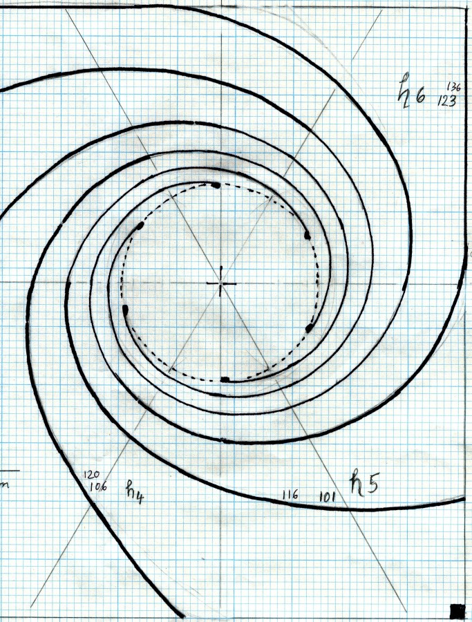
So I pushed and shuffed enlarged copies of the puck around until i managed to hand draw my new design for the 12 inch RCA driver.
Size is still about 33 by 39 inches, but to help the math I used 84cm by 100cm.
In this drawing all six horns have their throat in the circle of the speaker opening and I made the size 2cm wide. The horn guides will be 11cm tall, but I build this in two layers to get 22cm by 2cm horn throats.
I did the math starting with the Sd of 490cm square (27cm diameter).
Chamber volume will be 10.8 Liter
Total throat area is 2cm x 22cm x6 = 264cm square.
Upper cut off frequency works out to 133Hz - which I like, because from using these drivers in a Voight pipe I know only much lower frequencies were missing.
Horn length are h1 with 1.73m, h2 with 1.38m, h3 with 1.35m, h4 with 1.06m,
h5 with 1.01m and h6 with 1.23m
So now I need to get another sheet of ply for the second layer.
Yes I agree chazdrumzalot this will be huge, but given the location on the wall below the window and covered with a nice fabric it will nearly disapper and thank you for your input, I did work it in.
Lots of thanks to our untiring coach xrk971 who makes a lot possible.
Below are to pics which really should be one of my design using the "Puck" posted by xrk971. My paper was to big for the scanner, so anyone who wants to use it now needs to make two copies and tape them together right.
I think this design could be made smaller for 8 inch and 10 inch drivers if someone wants to get into uncharted areas. My best estimate for listening reports is two weeks from now (or3). (if I can't do this picture posting right, please visit my album)
Great tread this
So I pushed and shuffed enlarged copies of the puck around until i managed to hand draw my new design for the 12 inch RCA driver.
Size is still about 33 by 39 inches, but to help the math I used 84cm by 100cm.
In this drawing all six horns have their throat in the circle of the speaker opening and I made the size 2cm wide. The horn guides will be 11cm tall, but I build this in two layers to get 22cm by 2cm horn throats.
I did the math starting with the Sd of 490cm square (27cm diameter).
Chamber volume will be 10.8 Liter
Total throat area is 2cm x 22cm x6 = 264cm square.
Upper cut off frequency works out to 133Hz - which I like, because from using these drivers in a Voight pipe I know only much lower frequencies were missing.
Horn length are h1 with 1.73m, h2 with 1.38m, h3 with 1.35m, h4 with 1.06m,
h5 with 1.01m and h6 with 1.23m
So now I need to get another sheet of ply for the second layer.
Yes I agree chazdrumzalot this will be huge, but given the location on the wall below the window and covered with a nice fabric it will nearly disapper
and thank you for your input, I did work it in.Lots of thanks to our untiring coach xrk971 who makes a lot possible.
Below are to pics which really should be one of my design using the "Puck" posted by xrk971. My paper was to big for the scanner, so anyone who wants to use it now needs to make two copies and tape them together right.
I think this design could be made smaller for 8 inch and 10 inch drivers if someone wants to get into uncharted areas. My best estimate for listening reports is two weeks from now (or3). (if I can't do this picture posting right, please visit my album)
Great tread this
sealing up the last put-on-panel
I have an idea of sealing up the last put-on-panel properly :
- put the guides on the front panel (speaker mountings should have been properly prepared) using
hot melt gun, or anything good mentioned by other members. Nearly all projects so far put the
guides on the rear panel first.
- cut the 3/16 inch slots for the guides on the rear panel.
- With the guides facing up and the front panel facing the table, press the slots of the rear panel
on to the guides such that the guides just pop out of the rear panel surface (cant remember
the proper word). Use whatever glue or even hot-gun to stick ( and seal) the guides to the
rear panel. (This will look horrible if slots cut and sealing is done on front panel, oh
might be artistic).
Note the width of the guide should be wider by the thickness of the panel, for example
20 incher channels 2.8 inch deep and panel 3/16inch thick, the width of the guides should
be 2.8 + 3/16 inch.
This way will ensure the sealing is proper for the last put-on panel.
Any comment ??
Last edited:
Cutting the slots for the channels (or guides as you call them) will be a major hassle. In addition to being difficult to do in foam even, it weakens the rear panel. In wood it will require a router and a jig or very steady hands. Sort of defeats the point of the easy to make foam core spiral. The way to ensure a good seal is to do a good job in cutting the channels so that they have a uniform width. When this is done, the glue has no trouble sealing. It's good that you are trying to come up with a good way to seal, as a leak in the channel will render the horn useless at generating bass. Segmenting the back and gluing sections at a time is another way.
Not sure about the strength. The width of the slot does not need to be exact as the glue will seal up the imperfect gaps. I guess less time in cutting slots than trying to putting the glue on the right place. Apart from time spent, using this method I will be very sure the slot is sealed while in other methods there is still a question mark.
After sealing, sticking another board onto it might help strengthen the structure.
After sealing, sticking another board onto it might help strengthen the structure.
Glowglass,
Those are great looking plans you have. Thanks for sharing the scans. I think the plans would be very suitable for a smaller driver simply by making only a single layer spiral. Probably an 8 inch driver. 2 cm x 12.5 cm deep x 6 = 150 cm squared for 5 in deep channel. Cutoff high freq about 220 Hz. This opens the flood gate for anyone wishing to try a 8 inch full range like a BG20, a bofu, Fostex, Betsy, ...
Those are great looking plans you have. Thanks for sharing the scans. I think the plans would be very suitable for a smaller driver simply by making only a single layer spiral. Probably an 8 inch driver. 2 cm x 12.5 cm deep x 6 = 150 cm squared for 5 in deep channel. Cutoff high freq about 220 Hz. This opens the flood gate for anyone wishing to try a 8 inch full range like a BG20, a bofu, Fostex, Betsy, ...
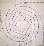
20 inch plan with custom channels
As requested, here is a photo of my original 20 inch plan with internal corners and a larger throat. The grid is 1 inch scale.
Your work and contribution are very impressive. I plan to build a 20 inch speaker with Vifa TC9FD. Noting that you have changed the throat width, would you mind to share a print of your 20 inch plan ?? I hope to get a successfuly reproduction. Thank you in advance.
By the way I have also gone through the other 100+ pages Foam Board thread and cant find your 20 inch plan as well. I only find the original sebastian and planet10 plans.
As requested, here is a photo of my original 20 inch plan with internal corners and a larger throat. The grid is 1 inch scale.
Attachments

- Home
- Loudspeakers
- Full Range
- Ever think of building a Cornu Spiral horn? Now you can!