Right, nearly done, that was a learning curve. I ended up improvising such is the nature of the beast when you get going. In photo's:
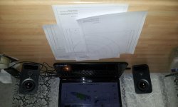
1. As I wanted a fully curved spiral I used the attached pdf's and stuck them together, leaving some of the margins to aid overlap. The donor speakers are in the background (Logitech Z150).
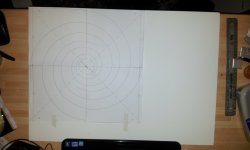
2. I stuck the template to the 5mm board on one edge only (so I could lift it like a flipbook if need be)
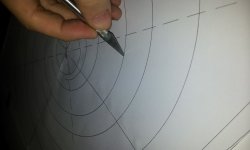
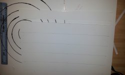
3. I then put a scalpel mark through the paper template into the foam. This gave me a “breadcrumb trail” on the foam.
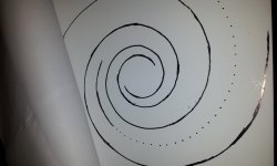
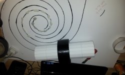
4. Tracing the scalpel marks, they were visible but for the benefit of the photo I've dotted them on in black. I also marked the center point later on (first mistake as I had to realign the template) and the corners. The template can become confusing with so many lines but the dashed diagonals helped.
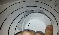
5. I drew 2” strips along some 3mm board and the slim excess piece at the bottom became my test section. I then experimented with shaping etc and glued it to an excess area of 5mm board.
6. Learning of the springback effect I formed the approximate shape then used sellotape to retain the form on the main rib.
7. This was a p.i.t.a there must be a better way (there are many) but I realised I could blu-tac the path then fix the spiral ribs to this, then use stronger tape on the top.
This worked well and they retained their form easily, I soon had all of the pieces done (but the tape needed trimming with scissors to stick it down). I also realised (see later) that there were much quicker ways of doing this.
8. Either way, I prepared the other long rib similarly.
I used the syrupy Gorilla glue and fixed the parts to the board then left them to cure (after spraying with water). It would have been much easier with longer lengths of 3mm board but this was all the shop had so I had to go in shorter stages worst luck.
9. For the second speaker I'd learned a lot from the first. It's quicker to score across all of the ribs on one sheet before they are separated into 2” strips. Yep, it's obvious now I know. It's also not important how far apart the scoring is either as long as it honours the curve so I went for approx 15mm intervals. The ribs as a whole were then pre curved to stop springback (a bit too successfully, especially for the straighter sections nearer the edge), before being cut into 2" strips and undergoing similar again.
I used household items to fix the shape of the spiral but it wasn't dynamite, back to blu-tac placed just off centre to act as temporary formwork.
The original pdf template was useful again as I blu-tacked it and prepped the rest of the ribs on that instead (as both units were clamped and out of action whilst the longer ribs cured). It's much quicker to just put a single piece of tape along the back edge instead of many strips that are constrained by the curvature of the top edge (and then needing slits cutting with scissors).
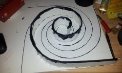
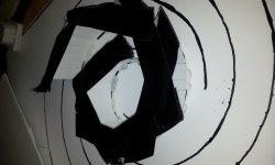
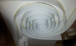
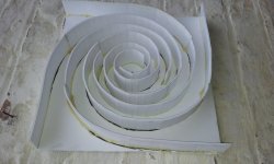
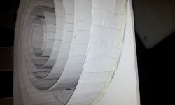
10. Upon stripping, the shape was very good and the ribs were glued securely. However the endeavour wasn't without failure. Some of the joints weren't that good but I will go over these will glue (and/or fill in with putty/blu-tac) later.
I don't have a glue gun, but now I know my way around gorilla glue I'll just hold it in place with that, this is quicker but more awkward than pre-forming the ribs beforehand though and the other methods you've all discussed might have been taken in more but Ive read that much it all became a blur.
That's it so far. Due to uneven distribution of clamping weights (piles of dvds, tin cans etc) the boards have warped a little, I will apply loads to try and bend them back or if need be trim the top of the foam flush with the scalpel. It's not too much of a warp.
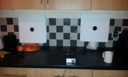
Next, I'll cut the front and back panels to size, seal up the internal surfaces, then apply a generous amount of expanding Gorilla Glue to the spiral top edge and fix the rear panel. I'll probably cut the driver hole out of the front panel first.
I have a few T Amps lying around so I might use one of those instead of the amplification that comes with the Logitech unit (I also have a 1.5W OTL too but I'll leave that out of it) although I haven't figured out what to do with cabling (prob a small hole in the back then sealed).
Many thanks folks for any further advice or comments, I hope my experiences also help out others.
Fingers, eyes and legs crossed.")
Edit: I've no idea why some of those photo's are upside down they're fine at this end. Awkward to correct in here too as it puts the sequence out of order. Hope they help anyway
1. As I wanted a fully curved spiral I used the attached pdf's and stuck them together, leaving some of the margins to aid overlap. The donor speakers are in the background (Logitech Z150).
2. I stuck the template to the 5mm board on one edge only (so I could lift it like a flipbook if need be)
3. I then put a scalpel mark through the paper template into the foam. This gave me a “breadcrumb trail” on the foam.
4. Tracing the scalpel marks, they were visible but for the benefit of the photo I've dotted them on in black. I also marked the center point later on (first mistake as I had to realign the template) and the corners. The template can become confusing with so many lines but the dashed diagonals helped.
5. I drew 2” strips along some 3mm board and the slim excess piece at the bottom became my test section. I then experimented with shaping etc and glued it to an excess area of 5mm board.
6. Learning of the springback effect I formed the approximate shape then used sellotape to retain the form on the main rib.
7. This was a p.i.t.a there must be a better way (there are many) but I realised I could blu-tac the path then fix the spiral ribs to this, then use stronger tape on the top.
This worked well and they retained their form easily, I soon had all of the pieces done (but the tape needed trimming with scissors to stick it down). I also realised (see later) that there were much quicker ways of doing this.
8. Either way, I prepared the other long rib similarly.
I used the syrupy Gorilla glue and fixed the parts to the board then left them to cure (after spraying with water). It would have been much easier with longer lengths of 3mm board but this was all the shop had so I had to go in shorter stages worst luck.
9. For the second speaker I'd learned a lot from the first. It's quicker to score across all of the ribs on one sheet before they are separated into 2” strips. Yep, it's obvious now I know. It's also not important how far apart the scoring is either as long as it honours the curve so I went for approx 15mm intervals. The ribs as a whole were then pre curved to stop springback (a bit too successfully, especially for the straighter sections nearer the edge), before being cut into 2" strips and undergoing similar again.
I used household items to fix the shape of the spiral but it wasn't dynamite, back to blu-tac placed just off centre to act as temporary formwork.
The original pdf template was useful again as I blu-tacked it and prepped the rest of the ribs on that instead (as both units were clamped and out of action whilst the longer ribs cured). It's much quicker to just put a single piece of tape along the back edge instead of many strips that are constrained by the curvature of the top edge (and then needing slits cutting with scissors).
10. Upon stripping, the shape was very good and the ribs were glued securely. However the endeavour wasn't without failure. Some of the joints weren't that good but I will go over these will glue (and/or fill in with putty/blu-tac) later.
I don't have a glue gun, but now I know my way around gorilla glue I'll just hold it in place with that, this is quicker but more awkward than pre-forming the ribs beforehand though and the other methods you've all discussed might have been taken in more but Ive read that much it all became a blur.
That's it so far. Due to uneven distribution of clamping weights (piles of dvds, tin cans etc) the boards have warped a little, I will apply loads to try and bend them back or if need be trim the top of the foam flush with the scalpel. It's not too much of a warp.
Next, I'll cut the front and back panels to size, seal up the internal surfaces, then apply a generous amount of expanding Gorilla Glue to the spiral top edge and fix the rear panel. I'll probably cut the driver hole out of the front panel first.
I have a few T Amps lying around so I might use one of those instead of the amplification that comes with the Logitech unit (I also have a 1.5W OTL too but I'll leave that out of it) although I haven't figured out what to do with cabling (prob a small hole in the back then sealed).
Many thanks folks for any further advice or comments, I hope my experiences also help out others.
Fingers, eyes and legs crossed.
Edit: I've no idea why some of those photo's are upside down they're fine at this end. Awkward to correct in here too as it puts the sequence out of order
. Hope they help anyway Attachments
-
 20131130_201743.jpg197.2 KB · Views: 489
 -
 20131130_203722.jpg727 KB · Views: 476
 -
 20131130_204052.jpg758.6 KB · Views: 463
 -
 20131130_210540.jpg781.1 KB · Views: 455
 -
 20131130_211814.jpg818.3 KB · Views: 440
 -
 20131130_213533.jpg860.6 KB · Views: 126
 -
 20131130_234447.jpg193.9 KB · Views: 185
 -
 20131130_215903.jpg728 KB · Views: 136
 -
 20131130_221841.jpg897.5 KB · Views: 178
 -
 20131201_191956.jpg840.5 KB · Views: 166
Last edited:
The .pdf spiral templates as mentioned. These are set up for A4 and then joined together (for the 14"/355mm version).
The check dimension says 178mm but this is Cad rounding, 177mm is fine of course if you print it and it's a tiny bit off. If it's some way off then check your printer settings (no zooming etc).
I've an A3 version included also, in case any of you have access to an A3 printer.
If anyone wants A2, A1, A0 etc then shout up and I'll create and provide.
Best
Nathan
Attachments
Nathan,
Nice work! I have a few comments that I hope you try. Don't take it the wrong way as what you did is awesome but I think it looks like it may have been a little more didficult than it really is.
1. A hot melt glue gun is critical for building this as it is what makes it easy and fast. Trust me on this. You don't need a fancy one. I use a cheap $2 one that is a 10 watt unit for all my projects. It is covered on the outside with old molten hot glue and looks like hell but still works. The hot melt literally hardens in less than 30 seconds as you bend the channel with your finger to hold a section in place. Glue 6 in sections at a time. You will be able to perfectly command where the channel sets relative to the drawing on the back panel as you have a few seconds to adjust it as the glue hardens. I found Walmart to have the least expensive glue sticks at $7 for 100.
2. You should score the channels on the *Concave* side - I think you did he convex side. This allows the paper on the compressive side to come together and it compresses the foam to make a very smooth bend while the convex side gets bent under tension. You won't get any gaps in the foam as you bend it.
Gorilla glue is good for final capping operation but from what I have heard it can be messy as it oozes all over the place. PVA white glue works very well here as it doesn't expand and ooze out. It can be cleaned with a wet piece of tissue before it dries. Although you have to wait at least 6 hrs before you can use it.
Anyhow, just want to give you some feedback for the next time you try.
Great work and congratulations.
Many thanks guys!
1. Yes wise words indeed, I think if (when) I build more I will buy a glue gun for sure!
2. I get it, ha I didn't even think of that.
Thanks again, I will go over any joints with PVA now, I was only going to use Gorilla Glue when I put the "lid" on as it expands and I'm worried about any voids where the 3mm ribs meet the 5mm backing.
I suppose if I clamp well enough etc.
Some of the shorter sections are slightly misaligned too, I'll tidy these up first.
Many thanks all, I feel much more confident now.
Nath
I've been catching up on this thread over the last few days and it looks like it could be a fun and economical way to build some good sounding speakers..
I saw that someone mentioned the HIWave BM65's and was wondering if anyone had tried them yet?
I saw that someone mentioned the HIWave BM65's and was wondering if anyone had tried them yet?
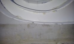
There was a small void at the joint between some of the panels so I filled these in with blu-tac.
Close up, the job looks a bit of a mess but it will be fine. To seal the enclosure, and mask the appearance too (even though it will be enclosed I know), I decided to spray the unit with a White Matt all purpose spray. I didn't use a primer as I've used the same stuff on many things in the past and they have all taken to it well.
Here's something you all knew, some sprays dissolve foam!
The paper is still all there but the foam has been slightly eroded in some areas, it's not too bad to fix at all (the paper is fine so I can fill the void with PVA) but even so that was another learning curve! (It's clearly the first time I've built anything from foam that much is obvious I admit).
The other speaker is untouched so of course that's fine, I'm half tempted to use this one as a sacrificial speaker to make sure I house the driver well etc and if so, reinstate it as a genuine finished article if it performs. I admit I'm tempted to start it all again with a glue gun and simply do it right first time, possibly using 5mm board for the ribs as the shop has it in longer lengths than 3mm.
Anyway, thought I'd share, the odd idiot putting the wrong foot forward now and again is a lesson for us all!
In photo's:
1. The unit before spraying. You can clearly see the expanded Gorilla Glue (which expands after some curing time rather than on application).
2. Some panels within the rib are now indented due to foam erosion, this is only nearer the very outer edges, the ribs nearer the driver are fine.
3. Some of the voids run the full depth of the score, of course where the spray could easily penetrate the material.
On the top edge (exposed to the spray) it is hollowed out by around 2mm, at least it will make for a natural shutter when gluing the rear panel!
Best
Nathan
Attachments
Last edited:
UnaHM,
Looking forward to seeing your build. Do what I do when your normal day job gets in the way of DIY : sleep less!
Haha, my nearly-2-year-old helps with that!
The DIY bug is definitely a problem of mine - I have to use my time wisely...research while I'm at work, so I can implement when I get home and don't have anything else to do!
I'm using a Muse T Amp to drive these speakers, a TA2020 I bought years ago, I'm enjoying them greatly.
I'd like to use a flea powered tube amp something the size of a tube headphone amp, the kind on Ebay for £30. Trouble is they of course have a 3.5mm jack and not speaker terminals (also Im not sure of their power). Has anyone else messed about/modded something like this and used it to drive the micro cornus?
Best
Nathan
Last edited:
Nathan,
If you want something the size of a headphone amp to drive your Cornu's, try the TPA3110D2 class D amp made by Sure. It is the size of a credit card and puts out a clean 6 watts/ch at less than 0.1% THD with 12 volt supply. It can be driven by 6 volts even at lower power. Sounds very good and a total deal at $10 from PE. Dont let the price or size fool you, this amp sounds really good. The headphone amps may not work with regular drivers as headphone amps are designed for 32 ohms or even 600 ohms.
http://www.parts-express.com/2x8w-@-4-ohm-tpa3110-class-d-audio-amplifier-board-only--320-329
Last edited:
They look great Nathan!!
Never tried it myself but also read really good reviews on that Sure amp.
From the time being I'm driving them with a lm1875 chipamp and sounds great now. Anyway I thought it would be nice to build a tube amp for the cornus I built.
Being a guitar amp guy, I have several preamp and power tubes ( 6l6s, el34s, el84s, ecc82, ecc83, 6sl7gt...) Single ended would be perfect!! And sticking to ecc83s would be great as I own a lot of them in different vintage brands for tube swapping.
Any ideas???
Sorry about the offtopic!!!
- Home
- Loudspeakers
- Full Range
- Ever think of building a Cornu Spiral horn? Now you can!