Chaz,
The design has solid bass extension to 50 Hz (90 dB) and will only have 75 dB at 35 Hz. This is at 3 meters away. You are going "off-reservation" if you make the 2-horn version - I can't guarantee the 35 Hz extension because there are a lot of things at play here: throat, chamber volume, channel width, mouth expansion ratio end-correction. Making a mouth expand greater than original will reduce extension. I would be patient and do both passages - you will get a better sounding product.
X
Chaz,
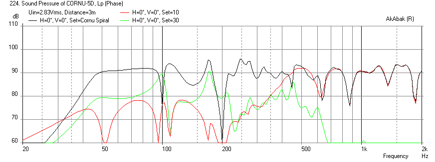
The response curve for the 1.2m above floor case on post 880 I think is below. It starts to decrease at 50 Hz and has output at 75 dB at 35 Hz - don't know if you call that substantial. The Panpipe pentahorn BLH design on the FC thread goes to 30 Hz before it starts to decrease, but that is a completely different design that is my own and optimized from the ground up for the W5-1611.
Here is the Cornu response with the W5-1611and front horn
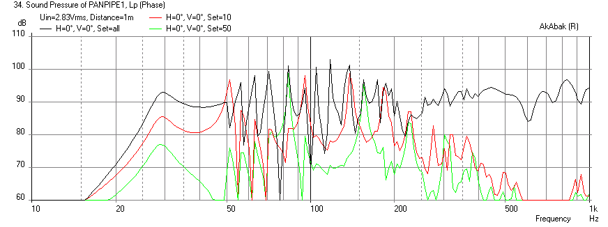
Here is Panpipe BLH with the W5-1611
Maybe you are mixing the two up?
The response curve for the 1.2m above floor case on post 880 I think is below. It starts to decrease at 50 Hz and has output at 75 dB at 35 Hz - don't know if you call that substantial. The Panpipe pentahorn BLH design on the FC thread goes to 30 Hz before it starts to decrease, but that is a completely different design that is my own and optimized from the ground up for the W5-1611.
Here is the Cornu response with the W5-1611and front horn
Here is Panpipe BLH with the W5-1611
Maybe you are mixing the two up?
Last edited:
This is the one I'm talking about.
The panpipe looks pretty sick, by the way.") Anyway, since I went ahead and printed the two-horn design, I'll go ahead and make it; there's not much risk involved and there are a few other reasons why I'm hoping this design could be made to work. For example, the diamond-shaped baffle could be made out of 2'x4' boards which are widely available pre-veneered. If it doesn't work out then I'll go back to the 4-horn version!
Anyway, since I went ahead and printed the two-horn design, I'll go ahead and make it; there's not much risk involved and there are a few other reasons why I'm hoping this design could be made to work. For example, the diamond-shaped baffle could be made out of 2'x4' boards which are widely available pre-veneered. If it doesn't work out then I'll go back to the 4-horn version!
The panpipe looks pretty sick, by the way.
Anyway, since I went ahead and printed the two-horn design, I'll go ahead and make it; there's not much risk involved and there are a few other reasons why I'm hoping this design could be made to work. For example, the diamond-shaped baffle could be made out of 2'x4' boards which are widely available pre-veneered. If it doesn't work out then I'll go back to the 4-horn version!
Last edited by a moderator:
W4 Progress Report
Hi Guys
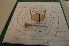
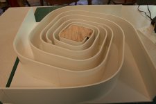
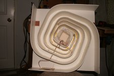
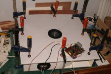
I thought I would post a few pics of my new Cornu's. I've done a few things a bit differently in terms of building method. After only an hr. listening with one clamped together I'm pretty satisfied and will glue up the front panels later.
Hi Guys
I thought I would post a few pics of my new Cornu's. I've done a few things a bit differently in terms of building method. After only an hr. listening with one clamped together I'm pretty satisfied and will glue up the front panels later.
Attachments
Thanks guys
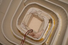
As it turned out I didn't have to cut into the channels at all. It's a snug fit but I think it's ok. The stuffing is a layering of poly felt pad cut to the shape of the chamber bottom then around the sides. I put some stuffing in 2 of the chambers with a string attached so I can pull it out if need be.
cheers- prez
OK, I'm hooked on these. They are a natural for having my cnc machine cut the channels in the faces. I have seen a couple of depictions of the spiral. One has more squared-off corners and the other is smoother. The smoother would be easier to bend foam core into. I can imagine these taking literally minutes to assemble once the channels are cut into say, some 3/8 or 1/2 inch plywood
As a first try, which one would you all recommend?
As a first try, which one would you all recommend?
I think they sound very similar. The smoother channels are easier to bend and probably lend themselves to your CNC channel milling technique. I assume you mean to cut grooves to fit the foam core board in? With grooves you can even fit thin softened or scored plywood as the channel material. Good luck.
Great! I've noticed that even the smoother one is not a "perfect" spiral. I have a spiral making gadget at my disposal that would make a "perfect" spiral. Would this be even "better", and if so how do I setup the criteria for it to plot it? I assume there is a length and expansion rate to keep in mind...
I'm jealous.
Tom, we have surmised the squared off corners in the true Cornu are acting as a filter to reduce the HF exiting the horn. There is no indication that I am aware of that says a true spiral is better. Because the squared corners will make the build more difficult then one has to assume there is value in retaining a similar shape. As far as the baffle material, I can't see it making much of a difference at 3/8 or 1/2, as they are supported so well by the spirals.
Tom, we have surmised the squared off corners in the true Cornu are acting as a filter to reduce the HF exiting the horn. There is no indication that I am aware of that says a true spiral is better. Because the squared corners will make the build more difficult then one has to assume there is value in retaining a similar shape. As far as the baffle material, I can't see it making much of a difference at 3/8 or 1/2, as they are supported so well by the spirals.
The spiral function is rather complicated. It is in fact called the Cornu spiral function and is a "clothoid" spiral. I have a Mathcad implementation of it somewhere back in this thread but the throat was very tight. The spiral used in the speaker design is probably a custom hand modified variant and no closed-form mathematical function exists that I know of. With al the work on programming the CNC tool path, gluing the foam channels onto a printed "tool path" like how we have been doing it on this thread might be just as easy. I think someone else CNC'd the channel with success in wood.
As far as programming the cnc, I've already imported the pdf. Since it is vectorized pdf (line drawing) it converts to a tool path rather "instantly". I'll double check the scale and get some foam board first to get the exact thickness before I cut it. I have some FF125wk drivers here for the test.
I would think you would have to use the double horn like the original as it's is tough to get the foam perfectly vertical so that it fits into the upper baffle piece if it were CNC'd. I think part of the reason for that center piece is as a guide to straighten them and make the alignment work. X, what's your take?
I still find myself wanting in the HF department. Maybe just my ears but...I have some FF125wk drivers here for the test.
I agree with Cal that getting the last plate with channels to fit will be near impossible. Hence the method of cutting a thru-slot in a middle divider plate and gluing to flats on both sides for ease of construction. If you are going to CNC this, why not just let the tool bit hog the entire thing out of a solid block of say, surfboard foam or other lightweight and relatively cheap material? Then glue just the top cap panel on as the base and channels are unibody construction machined out of a monolithic block. Stacks of glued together MDF to get appropriate thickness will work too but that is a lot of MDF to cut and throw away - very wasteful. Other materials that will work of course are plastics like Delrin, ABS, etc - but they are very expensive in such a thick block. Alternatively, the whole thing can be 3d printed in sections and assembled as one piece -also expensive materials wise. Nothing will beat the 5 panels of FC for $5 cost wise.
- Home
- Loudspeakers
- Full Range
- Ever think of building a Cornu Spiral horn? Now you can!