Working....
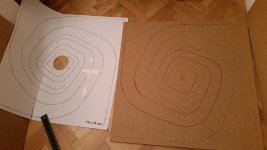
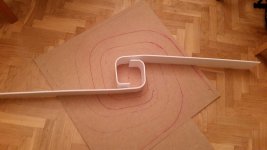
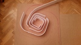
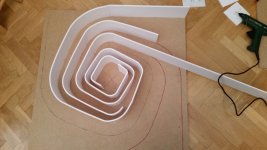
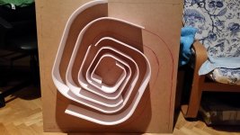
So up to now I've finished first Cornu and working around the second.
Here's some photos.
A couple of questions :
1) what do you use for "stuffing" and how do you distribute it inside? Are there any photos?
2) About fixing the front : I'd like to screwdrive instead of glueing so if I need adjustement it would be easy; what is your experience / warnings ???
Thanks a lot
giuseppe (madrid)
PD
Maybe useful put in the first post that foam name in Spain is "carton pluma" so if any other Spanish wants to try them will be easier.....
Attachments
Gmonno.
Nice progress there! Looking really good.")
1. Stuffing: I use synthetic polyfill (from old pillows), some people use rockwool, fiberglass, and even sheep's wool. Put some in the chamber and a small amount in the channels leading to the split. Some people put the stuffing in a porous nylon panthyhose sock with a string so it can be removed.
2. I don't recommend screws on the front panel as it is tough to get an airtight seal. Unless you machined grooves and had a soft foam gasket in the groove. I suppose if you had a large soft closed-cell foam sheet on the entire inside of the front panel, you could screw it on a the corners and a few more places near driver cutout. Easier to make sure it is all level and glue the top on with a big weight for a clamp.
Good luck!
Nice progress there! Looking really good.
1. Stuffing: I use synthetic polyfill (from old pillows), some people use rockwool, fiberglass, and even sheep's wool. Put some in the chamber and a small amount in the channels leading to the split. Some people put the stuffing in a porous nylon panthyhose sock with a string so it can be removed.
2. I don't recommend screws on the front panel as it is tough to get an airtight seal. Unless you machined grooves and had a soft foam gasket in the groove. I suppose if you had a large soft closed-cell foam sheet on the entire inside of the front panel, you could screw it on a the corners and a few more places near driver cutout. Easier to make sure it is all level and glue the top on with a big weight for a clamp.
Good luck!
portable Cornu boom box
Hello -
Here are some images of my initial sketches for this proposed design.
This box is 23" wide, 14" tall, 3" inside depth. I have Fostex FE1326E drivers on hand but could use any small inexpensive full range people recommend.
The idea is to drive these via small tripath amp boards mounted inside and powered by a AGM 12v battery.
The spirals are hand made, not generated by pure math. Am I close enough?
I experimented for a while with mathematically generated curves, but I ended up modifying these by hand until it looked right.
The spirals exit the cabinet front at the bottom.
I was thinking of making this out of multiple layers of plywood stacked with voids cut out of them. I also have a whole bunch of leftover bendy MDF from my big Cornu speakers (still incomplete), which might not be bendy enough for these radii.
I may also attempt a mock up out of foam core spirals inside a plywood box, to see how it sounds.
Any comments from those of you who know how to design speakers like these?
Colin
Attachments
Last edited:
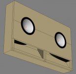
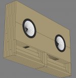
I spent some more time thinking about how to build these easily and make them look cool. Here are pics of a new version.
7 layers of 1/2" plywood, with spiral openings cut on the scroll saw, and layered together.
The plan is to cut all the sheets to full size, then print out the profile of each void, spray mount to the panels, cut, and then laminate into one block. Then, sand insides of spiral edges flush with a dremel, and trim outsides on the table saw so they are flush.
Thoughts? Worth building this design or should I factor in some input from this field of experts?
Attachments
Colinegreen,
Neat idea. It can work if you do the math on the horn right. What is your desired bass extension? Set length of horn equal to at least 1/4-wavelength of lowest note. Since it is an expanding profile, the length needs to be a bit longer even by about 10%. You also need to set the driver chamber volume and throat. The ratio of the throat to volume sets the upper cutoff frequency. Assuming an exponential profile these parameters can all be worked out for a straight horn. Your job is then to roll it up. Read up on back loaded horn design equations in MJK's papers on his website. You have not given any specifics of your horn sonI can't assess its efficacy. Need to know path length, expansion ratio from mouth to throat, throat area, chamber volume. You will need about 48in of path to hit 80Hz bass extension.
Neat idea. It can work if you do the math on the horn right. What is your desired bass extension? Set length of horn equal to at least 1/4-wavelength of lowest note. Since it is an expanding profile, the length needs to be a bit longer even by about 10%. You also need to set the driver chamber volume and throat. The ratio of the throat to volume sets the upper cutoff frequency. Assuming an exponential profile these parameters can all be worked out for a straight horn. Your job is then to roll it up. Read up on back loaded horn design equations in MJK's papers on his website. You have not given any specifics of your horn sonI can't assess its efficacy. Need to know path length, expansion ratio from mouth to throat, throat area, chamber volume. You will need about 48in of path to hit 80Hz bass extension.
Many thanks - I tried for some time to roll a specific horn around in a spiral, but (as I am sure you know) the outside of one part of the spiral is the inside of the next part, so everything overlaps quickly.
How long for 50 hz? Should I simply add more rotations of a profile which is getting wider at an approximately horn shaped rate?
I'll try again with another technique to spiral a horn once the straight horn is closer to right.
What is the formula for the diameter of the horn at a given length? I am using a generic exponential function to make mine.
Thanks for the help.
I'm not commenting on the design, but as soon as I saw these I had this in mid as a print on the front:

That'd be awesome!
What is the formula for the diameter of the horn at a given length? I am using a generic exponential function to make mine.
Thanks for the help.
You need about 75in long path to get 50Hz with an expanding horn. The ratio is always as big as you can make it in a practical enclosure. The regular Cornu has one of the largest expansion ratios for a BLH - about 1:25 most scoop type BLH's are about 1:5, no more than 1:10.
Hi friends! a year later my plan I begin to built a 60X60X8 cm cornu with chinese loudpeaker.
As soon I finish I'll get a feed back;the project is very fun, cheaper (for my choses) but I hope they can be my fantastic bedroom loudspeakers.
I think it will take some time becouse I'm using vinilyc glue and it take a very long time to dry
thanks to XRK971, CAL and every people who share informations and experiences in this very interesting thread.
XRK971 -
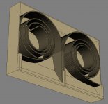
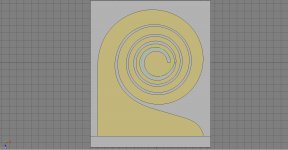
I have more or less completed a revised design.
This one has a horn roughly 100 " long, and goes from about 0.5" wide at one end to 14" at the mouth.
My question is the smallest radius section in the middle, closest to the driver.
I have made this smaller than the 4" speaker to allow for the most room for the horn to bend around and make a smaller overall box around the outside.
Do I want more space behind the driver or more loops of a wide horn spiraling around?
I can make the middle radius closer to 5" but this will allow few turns of the spiral or make the profile of the horn generally thinner.
The way I have set up my system for creating this spiral profile is super adjustable - it is a lot of tedious work, but it is pretty easy to modify it.
Smaller or bigger chamber behind the driver?
FYI the grid in the attached image has 1" squares, and the green circle in the middle represents the 4" hole in the baffle for the driver.
To remind you I will cut this spiral profile out of 6 layers of 1/2" plywood and stack them together with a solid back, and a baffle with a hole for the driver. (like the previous pictures...) 3" deep horn, 4" overall depth.
Comments? Improvements? I am happy to do one more before I start cutting.
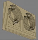
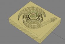
Also, the stepped mouth of the horn I showed before, which is an attempt to aim the opening of the horn forward is mainly to look cool like the Nagaoka designs which I like so much. I doubt it does much to the sound. Should I get rid of this and just leave the horn depth the same for each layer? If it does not make a difference, I will leave it as I think it looks cool. But if it robs bass extension I might leave it out. The second image - "improved_spiral_persp_v002.jpg) shows each layer WITHOUT the stepped depth on each layer at the widest part of the horn opening. I have not done this part yet as I don't want to go on until I learn if I should do this stepping or not.
The horns could also exit out the bottom, with the full depth of each horn (3"). I would have to raise it up on little feet so the sound is not blocked by what the speakers are sitting on. Or, I could flip things around so that the exit out the sides.
Thoughts?
I have more or less completed a revised design.
This one has a horn roughly 100 " long, and goes from about 0.5" wide at one end to 14" at the mouth.
My question is the smallest radius section in the middle, closest to the driver.
I have made this smaller than the 4" speaker to allow for the most room for the horn to bend around and make a smaller overall box around the outside.
Do I want more space behind the driver or more loops of a wide horn spiraling around?
I can make the middle radius closer to 5" but this will allow few turns of the spiral or make the profile of the horn generally thinner.
The way I have set up my system for creating this spiral profile is super adjustable - it is a lot of tedious work, but it is pretty easy to modify it.
Smaller or bigger chamber behind the driver?
FYI the grid in the attached image has 1" squares, and the green circle in the middle represents the 4" hole in the baffle for the driver.
To remind you I will cut this spiral profile out of 6 layers of 1/2" plywood and stack them together with a solid back, and a baffle with a hole for the driver. (like the previous pictures...) 3" deep horn, 4" overall depth.
Comments? Improvements? I am happy to do one more before I start cutting.
Also, the stepped mouth of the horn I showed before, which is an attempt to aim the opening of the horn forward is mainly to look cool like the Nagaoka designs which I like so much. I doubt it does much to the sound. Should I get rid of this and just leave the horn depth the same for each layer? If it does not make a difference, I will leave it as I think it looks cool. But if it robs bass extension I might leave it out. The second image - "improved_spiral_persp_v002.jpg) shows each layer WITHOUT the stepped depth on each layer at the widest part of the horn opening. I have not done this part yet as I don't want to go on until I learn if I should do this stepping or not.
The horns could also exit out the bottom, with the full depth of each horn (3"). I would have to raise it up on little feet so the sound is not blocked by what the speakers are sitting on. Or, I could flip things around so that the exit out the sides.
Thoughts?
Attachments
Last edited:
I modeled the driver itself with the specs on the profile from the manual. This brought two things to light -
1) The hole in my baffle was too small. (was 4" while the manual specifies 104mm or 4.09").
2) The radius of the inside opening of the horn is too small - it conflicts with the driver magnet. This means the center section has to be at least a tiny bit bigger (0.25" to 0.5" bigger radius).
So I need to go back and redo the spiral layout to make it fit the driver better. In the process, should I make it as small as possible and still fit, or as big as is reasonable within the same size box?
I know "Bigger Is Better" overall, but is a bigger chamber behind the driver better, even if the resulting horn gets smaller overall?
(is this volume of air behind the driver called the "throat"?)
Colin
Just finished building my 700mm cornus at 85mm depth. Used 5mm foam core for the inner spirals and worked out with 6mm plywood off-cuts that I bent after steaming between 2 saucepans. Plywood bends pretty well when its wet and hot, although the paper thin outside layer split on the most extreme bends. Once everything had cooled down the plywood was as strong as it started out.
Listening to these speakers in our ski apartment in Bulgaria right now.right laugh bringing them from the UK strapped to skis and covered in fragile tape. They came out first on the baggage lift!.
Using a £20 cheapo early original Tripath amp, 5 years old with Some really stupidity expensive output caps that I have no use for since everything else I have went DC coupled inc my car.lol. And they where going to waste.
Drivers are Visaton FR10s. Original stuffed the horns from mouth to 1st separation and found high end too much. Have pulled most stuffing out now and still want to remove what's left as the mid to highs are really above the low end output. Not sure if this is because I'm used to LX521s
Going to let them break in anyway as only been playing for a few hours. Will possibly be able to do the wizzer mod on the FR10s and put in a proper phase plug and put them higher up on the wall to take advantage of the ceiling shape.
Sorry if this post is a bit messed up as I'm posting from my Windows phone.
Brad. Picture to follow
Builder Brad,
Thanks for sharing! Strapped on skis to a ski hut in Bulgaria is a classic story. Are you AC coupling the drivers with the expensive cap that you mentioned ? Maybe that is high passing the driver and you get no bass. Try direct DC connection from Tripath.
I have not tried FR10 but should work and you should have bass down to 60 or 70Hz.
Cheers xrk971,
Those output caps where V Cap teflons @ 4.7uf. Pretty tight fit in the tiny amp case.
Not sure if I will be ok going DC coupled on the output on the TA2020 tripath amp. Don't have any way of testing or measuring DC offset out here either.
Have bass output, but the high end is more dominant. Might be the wizzer on the FR10s adding to that impression as well. Will probably make some phase plugs in the UK to bring out here next time.
Brad
- Home
- Loudspeakers
- Full Range
- Ever think of building a Cornu Spiral horn? Now you can!