Driver is FF85WK. The pipe tuning is based on the factory number for Fs, 115Hz - I ought to measure it for real in a serious build. Maybe I'll make a wood version come spring. Cross-sections for the three segments are 42cm^2, 62cm^2 and 87cm^2 respectively. The start and end of the line are pretty much that of the F-81 and I just went with a 1:1.4142:2 ratio for the central segment.
At 12ft, the F-81's 5/4 mode would fall close to driver Fs, but probably be too low in acoustic impedance to make much of a difference. Who knows, maybe even my 3/4-mode loading does not do much!") I wonder what was the rationale behind the F-81 design.
I wonder what was the rationale behind the F-81 design.
IG
At 12ft, the F-81's 5/4 mode would fall close to driver Fs, but probably be too low in acoustic impedance to make much of a difference. Who knows, maybe even my 3/4-mode loading does not do much!
I wonder what was the rationale behind the F-81 design.IG
Last edited:
IG,
I was just noticing that the overall aspect ratio of your F-81 box is very thin - could be wall mounted if you just put the driver on the big panel at the top corner. You would have to slightly modify the plan to allow clearance for the driver. Do you think double layer of foam core was necessary or could a lot of little braces have been used similar to how I made the FIB? If you have a freq response measurement of the pipe output that would be cool to see.
I was just noticing that the overall aspect ratio of your F-81 box is very thin - could be wall mounted if you just put the driver on the big panel at the top corner. You would have to slightly modify the plan to allow clearance for the driver. Do you think double layer of foam core was necessary or could a lot of little braces have been used similar to how I made the FIB? If you have a freq response measurement of the pipe output that would be cool to see.
IG,
I was just noticing that the overall aspect ratio of your F-81 box is very thin - could be wall mounted if you just put the driver on the big panel at the top corner. You would have to slightly modify the plan to allow clearance for the driver. Do you think double layer of foam core was necessary or could a lot of little braces have been used similar to how I made the FIB? If you have a freq response measurement of the pipe output that would be cool to see.
I prefer doubling-up the foam-core than using a ton of small braces, it's a faster process for me and I find it makes for a more rigid structure. The internal folds already brace it pretty well in this case too.
Blue trace = Driver output at 2"
Green trace = Vent output at ~2-3", with the cab's back to the wall, so effectively ~1/8 space from the mic's point of view
An externally hosted image should be here but it was not working when we last tested it.
Far-field response:
An externally hosted image should be here but it was not working when we last tested it.
Response at 60":
An externally hosted image should be here but it was not working when we last tested it.
We can see the 109Hz dip in the driver near-field measurement - which is where the actual ¾-wave mode lands, showing the pipe is tuned to 36.3Hz and probably does offer some acoustic impedance to the driver at Fs. We can see on the near-terminus response as well as far-field the peaking above 200Hz from the upper pipe modes. This should be suppressed with suffing.
Nice! I'm digging the stepped approach for the horn expansion.
I'd really hesitate to call that a horn though, it's really more an expanding TL.
IG
IG,
Thanks for posting the measurements - very nice! So you currently have no stuffing in the line at all? I might have to try doubling up the panels on one of my next projects.
Yep no stuffing at all. Sustained guitar notes in the 200-300Hz area are sort of annoying because of this.
How thick is your foam-core? I get the cheap stuff at the dollar store: 3/16" thick, 20"x30" sheets, 1.25$ a piece.
IG
Same stuff I use. $1 ea in the states. Readiboard (made in USA).
Bulk Readi-Board Foam Boards at DollarTree.com
Bulk Readi-Board Foam Boards at DollarTree.com
Greetings all!
Have read through all the way from the start of the thread till the last page, and I must say I'm definitely intrigued on how simple it is to build an enclosure out of foam board, especially when space is a big issue as I stay in an apartment on the sunny island of Singapore.
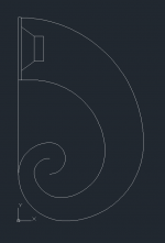
I'm more fascinated by the Fibonacci curve rather than the Cornu, reminds me of something I saw on a magazine a couple of years back, probably start a small build using old drivers from the satelite speakers of a Cambridge Soundworks (Amazon.com: Cambridge SoundWorks PCWorks Multimedia Speaker System, Black: Electronics , mine are white though).
Looks like you guys have another one joining the foam core group.
Have read through all the way from the start of the thread till the last page, and I must say I'm definitely intrigued on how simple it is to build an enclosure out of foam board, especially when space is a big issue as I stay in an apartment on the sunny island of Singapore.
I'm more fascinated by the Fibonacci curve rather than the Cornu, reminds me of something I saw on a magazine a couple of years back, probably start a small build using old drivers from the satelite speakers of a Cambridge Soundworks (Amazon.com: Cambridge SoundWorks PCWorks Multimedia Speaker System, Black: Electronics , mine are white though).
Looks like you guys have another one joining the foam core group.
For larger horn projects 1 am considering using this larger foam. Has anyone tried this stuff yet?Shop Rmax 1/2-in x 4-ft x 8-ft Polyisocyanurate Insulated Sheathing at Lowes.com
Attached is a rough design of what I'm thinking about.
Please bear with me, I'm not too sure about the technical terms of enclosures and such, do need a lot of guidance from the pros here.
This will be a really small build, said driver is about 2", with about 0.5"~1" surrounding the sides, which means the minimum width would be around 3"?
Any opinions on whether it will work out nicely?
P.S: First time I'm touching AutoCAD since 5 years ago, still trying to figure out how to add in measurements and such.
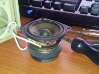
edit: The 2nd pic is the driver I'm considering to use, rated at 4ohms, 2W, feels pretty hefty for such a small thing...
Please bear with me, I'm not too sure about the technical terms of enclosures and such, do need a lot of guidance from the pros here.
This will be a really small build, said driver is about 2", with about 0.5"~1" surrounding the sides, which means the minimum width would be around 3"?
Any opinions on whether it will work out nicely?
P.S: First time I'm touching AutoCAD since 5 years ago, still trying to figure out how to add in measurements and such.
edit: The 2nd pic is the driver I'm considering to use, rated at 4ohms, 2W, feels pretty hefty for such a small thing...
Attachments
Last edited:
Ravener,
Interesting design... except that I am not sure what you are trying to do? Are you building a horn or a nautilus style transmission line (like the B&W Nautilus) where the spiral is acting as an infinite tube to prevent any back reflections? From the drawing it appears that you have the horn back loaded into a contracting spiral as a transmission line, which then re-expands out to a horn output. Is that what you are doing? If so, there will be a big loss in efficiency as the the profile is narrowing and then expanding.
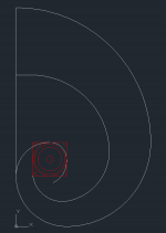
If I may suggest, I think you want to locate the driver at the narrow center of the 'snail' and not at the mouth. That's pretty good that you are able to draw a Fibonacci spiral in Autocad. I use Mathcad to develop the curves first and then import that to a CAD program. I used to use Autocad but have switched to SolidWorks a while back and glad I did it.
Interesting design... except that I am not sure what you are trying to do? Are you building a horn or a nautilus style transmission line (like the B&W Nautilus) where the spiral is acting as an infinite tube to prevent any back reflections? From the drawing it appears that you have the horn back loaded into a contracting spiral as a transmission line, which then re-expands out to a horn output. Is that what you are doing? If so, there will be a big loss in efficiency as the the profile is narrowing and then expanding.
If I may suggest, I think you want to locate the driver at the narrow center of the 'snail' and not at the mouth. That's pretty good that you are able to draw a Fibonacci spiral in Autocad. I use Mathcad to develop the curves first and then import that to a CAD program. I used to use Autocad but have switched to SolidWorks a while back and glad I did it.
How about this?
Dimensions will be around 13" by 8"(x) by 3" deep?
I have no spec sheet for the drivers though, not sure of their origins, and I doubt Cambridge Soundworks nor Creative would release them to a nobody like me.
They do sound rather bassy, but the original enclosure doesn't give it enough room to breathe.
Dimensions will be around 13"
by 8"(x) by 3" deep?I have no spec sheet for the drivers though, not sure of their origins, and I doubt Cambridge Soundworks nor Creative would release them to a nobody like me.
They do sound rather bassy, but the original enclosure doesn't give it enough room to breathe.
Attachments
That's some pretty funky designs there ravener. X, you think the venturi effect will cause a big downturn in efficiency? With foam board it looks like an easy one to try.
That's a different product. It's less flexy and is reminiscent of the stuff they used to stick fake flowers into. If you've ever dealt with phenolic insulation, they have a very similar profile. I think it would be good for straight sides but not for spirals or other curves.
Has anyone tried this stuff yet?
That's a different product. It's less flexy and is reminiscent of the stuff they used to stick fake flowers into. If you've ever dealt with phenolic insulation, they have a very similar profile. I think it would be good for straight sides but not for spirals or other curves.
@X - Frankly, the B&W Nautilus were the speakers I saw in the magazines, and as Cal mentioned, I was wondering if the venturi effect will work with soundwaves other than on a scramjet engine...
Reckon a big enough driver with high excursion will be able to push the air with enough force to compress it in the inner chamber and push it out with force?
Reckon a big enough driver with high excursion will be able to push the air with enough force to compress it in the inner chamber and push it out with force?
I am still missing the point why you want to go to a small cross sectional area only to expand again. It is like having a very large driver compression chamber, albeit a nice one that doesn't support reflected sound waves back out the cone like simple box chamber. The large nautilus compression chamber now has a throat located at the center of the snail and the actual 'horn' that radiates the sound is rather short. If you look at the upper cutoff frequency for a driver in compression chamber: fh = (c * S_throat) / (2 * pi * Vol), where c is speed of sound. I don't have the dimensions to calc the throat area and chamber volume, but this may limit how high of the bass notes that come out - it may be just fine but you need to look at it otherwise it may sound muffled. Then the output horn is so short, it won't really be good at amplifying the bass that comes out. The design is actually kind of like a BVR (Big Vent Reflex). If a BVR is what you are looking for then it may work. Cal is right though, with foam you can try this out and not lose anything but some time and a sheet of $1 foam core.
The second design with the driver in the middle is more like a horn, but now the driver compression chamber is so small that almost too much higher frequencies will leak out and you will ruin your spatial imaging. Also, the length of the horns will support the higher frequencies rather than the lower frequencies. You need lengths of order 4 ft or more on the path for bass frequencies. I think the spiral just needs more revolutions around the center to increase length. The horn is meant to provide a good impedance match for the high speed air that is coming off the speaker cone, and slow it down gradually, thereby increasing its pressure - which is why the sound level is amplified by the horn. I think if you expand the spirals further maybe 2.5 revolutions you will end up with something of order the size of almost a sheet of foam core (20 in x 30 in) and that will have the proper order lengths. The two different lengths are good as they can help smooth out dips and peaks from one horn - but you need to calculate the length difference to see how that looks.
Btw, this is not a curved venturi. A venturi does not have a sharp edged turn at the center, but is smooth everywhere to prevent sudden pressure drops which are irrecoverable. A scramjet engine looks like a venturi but is not a venturi. It is a supersonic diffuser (contracting cross section) + supersonic nozzle (expanding section) with a subsonic center section to support subsonic combustion of the fuel (fuel and air can't burn at supersonic speeds).
Last edited:
Ok, thanks for taking the time to explain.
Looks like there's no way to keep the design compact.
Guess it's back to the drawing board.
edit: Trying to do some calculations based on the formula you've provided. I'm bad at maths.
fh = (c * S_throat) / (2 * pi * Vol) //Vol is equal to the volume of the throat right?
fh = (330m/s * [pi*r^2]) / (2 * pi * [pi*r^2*h])
fh = (330m/s * [pi*0.0254m * 0.0254m]) / (2 * pi * [pi * 0.0254m * 0.0254m * 0.0762m])
fh = (330m/s * 0.002027) / (0.0009706)
fh = 689Hz
That can't be right...
Am I doing this wrong?
Last edited:
Ok, thanks for taking the time to explain.
Looks like there's no way to keep the design compact.
Guess it's back to the drawing board.
Put the driver on the other horn mouth and expand the length of the output horn to about 4 ft (gets you down to about 100 Hz). The size may be closer to 12 x 18 in. No harm in trying as it costs nothing!
If anything, you will learn the ins and outs of building curves in foam core and hot glue in the process and make much better builds later.Good luck!
- Home
- Loudspeakers
- Full Range
- Foam Core Board Speaker Enclosures?