Klampy,
If you stretch it in one direction, the path lengths of the nominally 2 x long and 2 x short horns will change to have 4 different lengths. This may be an advantage by having multi horn frequencies blend to be smoother in output frequency.
that makes pretty good sense actually. without specs on the driver (annoying as for a pro audio brand..) any suggestion on a recommended scale? driver has a pretty low Fs, like around 30-40hz. big power handling, and fairly subdued midbass/midrange output.
that makes pretty good sense actually. without specs on the driver (annoying as for a pro audio brand..) any suggestion on a recommended scale? driver has a pretty low Fs, like around 30-40hz. big power handling, and fairly subdued midbass/midrange output.
The 70 cm square has a nominal freq of 38 Hz according to longest path. If doing a 6 x9 you would need to scale the short dimension by 6/5 x 70 cm = 84 cm, and the long by 9/5 x 70 cm = 126 cm. It will be BIG looking, but very cool, with probably an average tuning freq down in the 25 Hz range - I am guessing, based on linear scaling arguments.... Give it a try
")
wow, thats bigger than the horn i was gonna do for my 8inch driver. (insert epic sad face here)
my biggest problem is the fact that im in the garage, at a computer desk with my laptop. i need/want something thats somewhat small enough to sit on my desk, on either side of my laptop, and still sound awesome.
if i run the 4inch coaxial drivers, it would be 70cm^2 still to attain a theoretical tuning of 38hz? even thats probably still a bit big, i only have 120cm from end to end of the table...
what im thinking is a rectangle box, 120cm wide, 60cm tall, (two squares) but with a single(maybe double) spiral so one exits the top, and one on each side of the main box.
that way, ill get good stereo imaging, and the bass will eminate from the top and sides of the cab.
so, any ideas what will happen differently having two spiral paths rather than four? the top one would actually become one mouth, rather than two as id twist the left one to spiral out anticlockwise, and the right one spiral out clockwise.
what you think?
Klampy,
The 4 in coaxials can probably work in the 50 cm (20 in) if you are trying to keep size small. The side by side stereo is a cool idea, mod the plan to have only 2 spirals on each side with outputs at top and sides. That's the fun and beauty with foam.... easy to try.
The 4 in coaxials can probably work in the 50 cm (20 in) if you are trying to keep size small. The side by side stereo is a cool idea, mod the plan to have only 2 spirals on each side with outputs at top and sides. That's the fun and beauty with foam.... easy to try.
absolutely. ok, so what i might do is wait till new years before i start this, as i have a cash injection heading my way at that time. id love to have a nice stained laquered front panel, so i think ill do it out of ply. it will make a nice backdrop on my desk for producing on. i think , based on me playing with digital EQ and DSP etc, i can make it work the way i need it to.
The TC9FD needs no tweeter, you would be adding the messy crossover into an otherwise Nice FR. Maybe a sub to make it into a FAST but no tweeter.
As I haven't listened to the Vifas yet, my reference to a two way was based on a couple posts I had read. Hopefully I'm in for a pleasant surprise.
Several years ago I bought a dozen buy-outs that have produced great bass in a couple different cabinets.
Stanford MSF100B20U
20 W
89 db
fs=68.5
vas=4 ltr
qms=1.86
qes=.43
qts=.35
to=3K
They matched the Audax I mentioned quite well. After I finish the 24" Vifa build I'll try another with that combo.
One forward - two back: The luan I planed to use was too old. As soon as I cut it to size the panels curled up and became unusable. I glued two opposing curves together and that resulted in a flat double panel. I'll buy some new wood today for the other two.
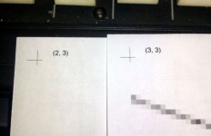
Also, I may have missed any suggestions of an easy way to sale the pattern to different dimensions. I ended up using Corel Draw in poster print mode. The PDF is offered for anyone interested in a 24" version. For super accuracy, there are match marks that can either be cut or one can use a pin or needle to punch through while taping the pages together. (May depend on printer driver)
Attachments
Planet10 made a very vector pdf plan for the cornu that you can scale. Somewhere back on page circa 40 something? You will be happy with the Vifa's top end. See Pano's measurement here:http://www.diyaudio.com/forums/full...building-cornu-spiral-horn-now-you-can-7.html
Thanks, I have that PDF and a couple others. I'm all set now, but for future reference what is suggested as the best method/software for doing the scaling. I created a 24" X 24" layout in Corel, cropped out everything (ledger line extensions) outside the edges of the foam and then manually adjusted all four sides to match the template. If there is an easier method - I'm all ears.
Planet10 made a very vector pdf plan for the cornu that you can scale. Somewhere back on page circa 40 something?
Here: page 23
Thanks, I have that PDF and a couple others. I'm all set now, but for future reference what is suggested as the best method/software for doing the scaling. I created a 24" X 24" layout in Corel, cropped out everything (ledger line extensions) outside the edges of the foam and then manually adjusted all four sides to match the template. If there is an easier method - I'm all ears.
Bob.
If you print the pdf using Adobe Acrobat Reader X (recent version 10.1.4), in the file/print menu dialog, there is an option under Paper and Page Handling called "Print Poster". Here, you can choose scaling in percent and give overlap and cut marks, etc. Using Planet10's pdf (http://www.diyaudio.com/forums/full-range/223313-foam-core-board-speaker-enclosures-23.html post #230 ) when I select "Print to Scale" it prints the cornu out as a 7.0 inch scale. So to get a 24 inch you need to scale 7.0x3.428=24.0 inches. So in this example scale the drawing by 343% and I selected 0.5 in for overlap to give enough room for taping or gluing them together. It will generate 15 pages (3x5) of 8x11.5 sheets that you will have to piece together. It may be helpful to select "Cut Marks" and "labeling" so you do not have to work it like a puzzle. I tested this and it works. For some reason it uses more paper when you select "Cut marks". Hope this helps.
xrk971
Last edited:
xrk971,
That is very generous of you to take the time. I have what I need for now but your math will be helpful for later projects and other builders. I did most of what you say but I was a little confused about the space outside the foam on that PDF. I went back for look at 6L6's photo to see if the foam went flush with the edge of the wood. That may be just an aesthetic consideration but I removed that extra before scaling. This entire design may not require that much detail, but I decided the slightly larger contained volume wouldn't hurt.
Thanks again.
P.S. Anyone need half a ream of good-one-side scratch paper?
Ignore space beyond outside extent of channels. The grid is just there for guidelines. I think everyone has been making the foam channels come out flush to edge of faces. You are welcome.
Good luck with the build and don't let the measurements coming out discourage you - it sounds really good.
Good luck with the build and don't let the measurements coming out discourage you - it sounds really good.
Last edited:
...
P.S. Anyone need half a ream of good-one-side scratch paper?
Put it back in the printer upside down, use it for your next project...
... and regarding the extension beyond the edge of the spirals, one of the original designs had two stacked spirals. The spirals were formed by cutting spiral slots in a central board and filling the slots with cut pieces of wood. The central board was therefore larger than the front and back panels.
Last edited:
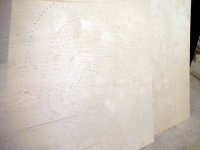
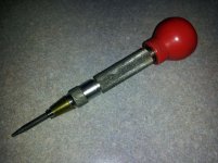
Whew!! Finally go some actual progress. I gave up the ghost and just bought two 2' x 4' x 1/4" birch plywood. Much better than working with the curvy old stuff. I used a spring loaded center punch relaxed to its weakest setting and had both panels done in 20 minutes.
Just to double check, I should use the same 4.5" strips even though the build is only 24" compared to the full 30" size, correct?
Might have music by tomorrow night.
Just to double check, I should use the same 4.5" strips even though the build is only 24" compared to the full 30" size, correct?
Might have music by tomorrow night.
Attachments
Strip depth or channel height depends on driver Sd. Which driver were you using again?
The Vifa TC9FD-18-08.
The 4.5 in was for the 70 cm size with Fostex FF125wk. Vifa is smaller, measure your throat width that you just drew with the punch. That width x channel height x 2 needs to approximately equal Sd for Vifa tc9fd which Is 36.3 cm square, if I recall correctly.
Last edited:
I just checked my old 20 in cornu plan. It was hand drawn by me and I made mods as I went along so it does not follow the plan of Planet10's pdf layout if scaled to 20 in. My throat widths were custom adjusted to 1.2 in wide. Thus my channel depth is 2.34 in ( I picked 2 and 3/8 for convenience). If you scale your pdf drawing down to 24 in, the throat, I believe will only be 0.6 and this means depth needs to be 4.7 in. This may be reason others who built the 20 incher using the pdf scaled will have too small of a throat?
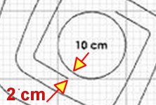
Throat = 2 cm x 2 = 4 cm
4 x 9 = 36 = 3.52" width.
Correct?
No, the circle has nothing to do with it. That is cutout hole. The gap is from innermost channel edge to next adjacent channel wall.
- Home
- Loudspeakers
- Full Range
- Foam Core Board Speaker Enclosures?