Certainly a foam of flattery.
attached.
dave
In the patent - this is the first time I have seen a deflector cone at the bottom of the driver cavity. I wonder if this is needed or helps? Planet10, you have apparently been following this speaker design for a while now as you have the patent on hand. If you don't know German, it is hard to understand compared to the Romance languages. If this was a standard pdf we could translate it with google.
@sprokeT i get mine from officeworks. Its not "cheap" at 10.30 a sheet, but it is compared to the price of wood. And it comes in different colours  . Check the posterboard section.
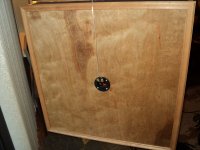
Xrk, yes its another th with a common mouth. Four drivers, one on the front on each side and one inverted on the mouth. i couldnt get any other design to simulate a low enough response. This design is winning so far. My first go sims at a peak of 125hz and also measures the same. So im sure this one will be much better.
. Check the posterboard section.Xrk, yes its another th with a common mouth. Four drivers, one on the front on each side and one inverted on the mouth. i couldnt get any other design to simulate a low enough response. This design is winning so far. My first go sims at a peak of 125hz and also measures the same. So im sure this one will be much better.
In the patent - this is the first time I have seen a deflector cone at the bottom of the driver cavity. I wonder if this is needed or helps?
I wondered about that too. Also, see that platform that gets thicker towards the middle? That would insure more of a true horn shape for each channel.
I wondered about that too. Also, see that platform that gets thicker towards the middle? That would insure more of a true horn shape for each channel.
You mean the "Tower of Babel" design?
It is cool but a fabrication nightmare. I am not sure if having a horn that expands in both dimensions makes it perform better. We have a cross sectional area expansion in one dimension now and from all accounts, it seems to generate sufficient bass to fill in with the mid and high end. Note how they also score the plywood channels on the inside to make the bends.@sprokeT i get mine from officeworks. Its not "cheap" at 10.30 a sheet, but it is compared to the price of wood. And it comes in different colours
Xrk, yes its another th with a common mouth. Four drivers, one on the front on each side and one inverted on the mouth. i couldnt get any other design to simulate a low enough response. This design is winning so far. My first go sims at a peak of 125hz and also measures the same. So im sure this one will be much better.
Ouch!!!
Even in Australian dollars, $10/sheet hurts. Not sure if I would play with it at that price. You can get plywood here in the states at that price. At least the Sureply underlayment that Cal is using is around that price. That's an interesting design to have two drivers one at mouth and another in the back - where did you get this design or was it your own? Are there phase cancellation issues?Ouch!!!
yes, tis a little exxy, but i dont mind, the first batch was free, so its only cost me once, and its good quality stuff.
That's an interesting design to have two drivers one at mouth and another in the back - where did you get this design or was it your own? Are there phase cancellation issues?
nup, all my own concept, obviously i was only able to measure/sim the design with one driver, but the reason ive layed it out like this is for maximum space use. as im very limited with space under a laptop, it has to be very compact yet still offer a decent mouth size, and fit a certain length horn path inside.
also, i noticed that if i pinched the mouth opening slightly i actually got an increase in bass output, so having the driver in the mouth is hopefully going to gain me a bit of deep bass by acting as a bit of a physical filter/plug.
as far as phaze issues, im not sure yet. according to the sim i get a big deep notch at about 225hz, which IMO is fine, coz i usually drop the EQ slider around that freq anyway.
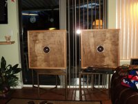
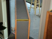
im aiming this one to be a bit more visually appealing, so i dressed up the front driver with some black vinyl dye, and i plan on dressing up the outside of the box properly, like i planned with the original but never got to.
ive been using dressmakers pins to hold the panels while the glue dries and it seems to be working quite well. and using PU glue in fine beads. which also worked well on the previous box. (just used a bit too much tho i think... lol)
anyway, my internet shoudl be fixed this thursday (fingers crossed) and ill be able to put up pics as they happen, rather than using works internet...
Progress, and I want to tell you about a sign from god. [must be 'cause I'm not that smart and I don't know who else to give the credit to.]
I have been wondering about attaching the trim pieces. I want it to be fairly fast as I am an impatient person. I want it to be fully adhered, not just spot adhered to reduce the chance of buzzing. I would like to use hot glue but the run is too long so I was settling on wood glue. Damn, wood glue takes a while to set up and needs lots of clamps. Hmph! Then it hit me. Lay a bead of wood glue with small gaps at set intervals. Use hot glue in the gaps and voila! Fully adhered and the hot glue does the clamping. They were done in no time. Wahoo!
I have a lot of cleaning to do before I mount the drivers so no pics yet but I'm sure I'll have them in a bit.
I also notice how the quality of workmanship goes downhill post-rum so last night's effort was well, how do you say...
...nah, I not saying anything, they'll be fine.
Progress, and I want to tell you about a sign from god. [must be 'cause I'm not that smart and I don't know who else to give the credit to.]
I have been wondering about attaching the trim pieces. I want it to be fairly fast as I am an impatient person. I want it to be fully adhered, not just spot adhered to reduce the chance of buzzing. I would like to use hot glue but the run is too long so I was settling on wood glue. Damn, wood glue takes a while to set up and needs lots of clamps. Hmph! Then it hit me. Lay a bead of wood glue with small gaps at set intervals. Use hot glue in the gaps and voila! Fully adhered and the hot glue does the clamping. They were done in no time. Wahoo!
I have a lot of cleaning to do before I mount the drivers so no pics yet but I'm sure I'll have them in a bit.
I also notice how the quality of workmanship goes downhill post-rum so last night's effort was well, how do you say...
...nah, I not saying anything, they'll be fine.
I did the same thing by using combo hot glue to clamp or tack in pkace and white pva to glue and seal the foam channels on my first one. The truth is I was running low on glue sticks and did this to conserve but found it works well as a clamp. Serendipty and necessity is the mother of invention.
From the Peanut Gallery:
For attaching trim, tightly-stretched blue masking tape every two inches (perpendicular to the joint) or so works fine with wood glue. It's routinely used to apply trim to kitchen countertops, etc. Also, if you feel rushed, Elmer's white glue is just as good as Titebond and sets up more slowly.
Doug
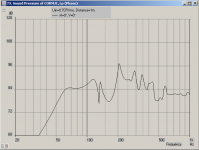
OK, I printed Dave's PDF, dimensioned it, built an AkAbak model, scaled it to Cal's size (70 x 70 x 11.5 cm) and used Fostex FF125K T-S specs. The results are attached.
- The dimensions are "all over the map". The plan needs redrawing to make the horn sections taper more evenly. The "round spiral" cornu plans may be better.
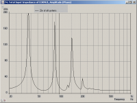
- There are multiple resonances, as indicated by the SPL and impedance curves. Note the behaviour around 150 Hz. I did not include stuffing, so real life won't look as bad as the model.
Next step is to make an "ideal" AkAbak model - regular horn tapers. I have my doubts about the multiple path length horns, I'll try it with single length paths too.
- The dimensions are "all over the map". The plan needs redrawing to make the horn sections taper more evenly. The "round spiral" cornu plans may be better.
- There are multiple resonances, as indicated by the SPL and impedance curves. Note the behaviour around 150 Hz. I did not include stuffing, so real life won't look as bad as the model.
Next step is to make an "ideal" AkAbak model - regular horn tapers. I have my doubts about the multiple path length horns, I'll try it with single length paths too.
Attachments
OK, I printed Dave's PDF, dimensioned it, built an AkAbak model, scaled it to Cal's size (70 x 70 x 11.5 cm) and used Fostex FF125K T-S specs. The results are attached.
- The dimensions are "all over the map". The plan needs redrawing to make the horn sections taper more evenly. The "round spiral" cornu plans may be better.
- There are multiple resonances, as indicated by the SPL and impedance curves. Note the behaviour around 150 Hz. I did not include stuffing, so real life won't look as bad as the model.
Next step is to make an "ideal" AkAbak model - regular horn tapers. I have my doubts about the multiple path length horns, I'll try it with single length paths too.
Great! Someone finally modeling this thing. How do you model the split lengths? The sound that Cal describes appears to be lots of bass, whereas the sim is low on bass with lots of mid range peaks. Do you mind scaling it to 20 in (50 cm) and running it with the Vifa tc9fd- assume round spirals if it helps? Also, at the 70 cm, the longest path should get down to about 38 Hz, the sim shows falloff below 50 Hz. Thanks for tackling this.
That would work if the baffles weren't freshly oiled.For attaching trim, tightly-stretched blue masking tape every two inches (perpendicular to the joint)
Yes, but that peak at 200 Hz is very apparent. Stuffing will be the key here.The sound that Cal describes appears to be lots of bass
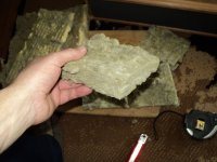
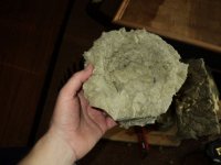
I have the trim applied and did the following stuffing:
First is the horn throat stuffing, worked into place with fingers and a spoon.
Next is the birds nest I created for the driver.
Last is the view of the chamber when stuffed.
First is the horn throat stuffing, worked into place with fingers and a spoon.
Next is the birds nest I created for the driver.
Last is the view of the chamber when stuffed.
Attachments
That stuffing sucked the life out of the system. Limited bass but the mids returned. I guess that was too close to aperiodic.
Removed the throat insulation and left the chamber with the birds nest. We are getting close now. Some of that 200Hz is still there but with a touch of throat insulation I am guessing we can look after that.
Removed the throat insulation and left the chamber with the birds nest. We are getting close now. Some of that 200Hz is still there but with a touch of throat insulation I am guessing we can look after that.
The stuffing sucked the life out of the cabinet. Limited bass but the mids returned. I guess that was too close to aperiodic.
Removed the throat insulation and left the chamber heavily stuffed. We are getting close now. Some of that 200Hz is still there but with a touch of throat insulation I am guessing we can look after that.
Cal,
Thanks for the minute play by play with your adjustments. Are you using a spectrum analyzer? Even software one using the computer mic is helpful.
I am listening to mine now and think that I must have just gotten lucky with the light stuffing i put in the throat.
Xrk971
- Home
- Loudspeakers
- Full Range
- Foam Core Board Speaker Enclosures?