Both, as you proved.Foam core or similar construction can't handle much in the way of pipe TL/horn action. Great for damping high Q systems where the cab's 'breathing' is ~uniform though.
GM
With that 100 Hz peak removed, would you say that this is a pretty flat frequency response from 30 Hz to 2kHz before cone-breakup? With a XO set at 2kHz and a better tweeter this could be a nice speaker. This is my first speaker with a true 30 Hz extension and I have to say that my ears and body 'feel' it more than here notes down there.
I believe there are only two left in my little town, but I'm hoping to be able to listen to one of the large pipe organs this winter to refresh the sensation of hearing/feeling that bottom register. One is in a church with such good acoustics that the local symphony plays there from time to time even though the program may not include any organ stuff.
Will be interesting to determine how close one can get without building massive boxes - considering the advanced driver technology available today.
Will be interesting to determine how close one can get without building massive boxes - considering the advanced driver technology available today.
Both, as you proved.
GM
With that 100 Hz peak removed, would you say that this is a pretty flat frequency response from 30 Hz to 2kHz before cone-breakup? With a XO set at 2kHz and a better tweeter this could be a nice speaker. This is my first speaker with a true 30 Hz extension and I have to say that my ears and body 'feel' it more than hearing notes down there.
With regards to massloading the cap, have you considered that a double walled cab with sand or leadshot in between could be a very good approach to a finished non-prototypeish speaker?
You'd need some anchor points/spacers to bind the two walls together so they won't bend and ultimately break under the load, but otherwise this could be a very good approach to building a speaker without a workshop. At the cost of a larger cab of course, but still.
1.5 inch walls maybe?
You'd need some anchor points/spacers to bind the two walls together so they won't bend and ultimately break under the load, but otherwise this could be a very good approach to building a speaker without a workshop. At the cost of a larger cab of course, but still.
1.5 inch walls maybe?
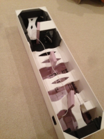
Construction of second XPS MLTL begins
I'm going to try a trick I used once before to reduce wall resonance. I put a layer of small dots of plumbers putty between two sheets of foam core bonded together with glue. I will do this for the top piece. The front where the driver is mounted has two layers of different stiffness foam core glued together with wood working aliphatic resin glue. I will add more bracing on the second one.
With regards to massloading the cap, have you considered that a double walled cab with sand or leadshot in between could be a very good approach to a finished non-prototypeish speaker?
You'd need some anchor points/spacers to bind the two walls together so they won't bend and ultimately break under the load, but otherwise this could be a very good approach to building a speaker without a workshop. At the cost of a larger cab of course, but still.
1.5 inch walls maybe?
I'm going to try a trick I used once before to reduce wall resonance. I put a layer of small dots of plumbers putty between two sheets of foam core bonded together with glue. I will do this for the top piece. The front where the driver is mounted has two layers of different stiffness foam core glued together with wood working aliphatic resin glue. I will add more bracing on the second one.
I put a layer of small dots of plumbers putty between two sheets of foam core bonded together with glue.
Why not just bond them with a flexible adhesive like me and some others do for constrained layer damping [CLD]? http://www.duspec.com/DuSpec2/produ...=70&productCode=LN-902&documentType=datasheet
GM
Why not just bond them with a flexible adhesive like me and some others do for constrained layer damping [CLD]? http://www.duspec.com/DuSpec2/produ...=70&productCode=LN-902&documentType=datasheet
GM
I have a tube of liquid nails but did not want to crack that open with caulk gun for this one project. Can't use it for the exterior main panel joints as it is not clear and may look messy. I suppose hot melt glue is also considered flexible but I wanted to add the putty because it actually has mass - probably clay content.
For exterior joints clear hot melt or white PVA are excellent for clean looks.
Am I missing something, I don't see a long board creating a transmission line in that pic. It looks like a well braced enclosure.
The TL is the 47 in long enclosure itself - there is no folded inner path. This is a straight mass loaded TL alignment where the port creates a constriction that pulls the resonance frequency lower - the analogy is added mass to the end of tuning fork to lower its resonance frequency - or "mass loading" it. Really it should be called constricted terminus TL.
Can't use it for the exterior main panel joints........
We're having a 'failure to communicate'.
It would be used to bond a slightly smaller perimeter panel to the inside of the exterior panels, leaving a gap all the way around, so that they can 'float'.GM
We're having a 'failure to communicate'.
GM
Ok, got it. Do you think liquid nails is softer than hardened hot melt glue? I just haven't bothered to open up a tube because my job is too small and the cartridge will dry up once opened. Need to put it in a resealable squeeze tube.
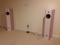
XPS foam & FC MLTL with PE 6.5 in Polycone driver - Build #4 (unit 2) - Completed
I finished the second unit and now have stereo sound. Initial listening tests with the pair sound very nice. Songs with a deep bass line especially sound good. Sound clips to come later...
Here it is being tested with a Lepai amp and 8 watts is pretty loud in my rec room.
I finished the second unit and now have stereo sound. Initial listening tests with the pair sound very nice. Songs with a deep bass line especially sound good. Sound clips to come later...
Here it is being tested with a Lepai amp and 8 watts is pretty loud in my rec room.
Attachments
actually it is bad if it moves or resonates... could be fun, but not accurate.
interesting idea though...
_-_-bear
I was just editing post #1 to update the index and noticed post #2 saying that foam core will not give accurate reproduction... I think the Nautaloss disproves that pretty conclusively.

http://www.diyaudio.com/forums/full-range/247598-nautaloss-ref-monitor.html
Last edited:
- Home
- Loudspeakers
- Full Range
- Foam Core Board Speaker Enclosures?