Thanks for the kind words and encouragement guys. I think it should sound even better once there is a back enclosure on. Right now it is running kind of like an open baffle horn.
It's pretty easy to build and I am sure other drivers work too. With four drivers the excursion on any one is very low. This may be what is helping to keep distortion down. The sound really carries far with he horn. I can stand at the back of the room and it still sounds like I am in front of it.
It's pretty easy to build and I am sure other drivers work too. With four drivers the excursion on any one is very low. This may be what is helping to keep distortion down. The sound really carries far with he horn. I can stand at the back of the room and it still sounds like I am in front of it.
One more time.
Many thanks!! Will build this after Thanksgiving. any chance that you have the whole article?? I'd like to read the front as well.
Regards,
Harvey/ Ga
Yeah, what they said. And it looks great. Kudos on an awesome build. Any chance on getting the dimensions of the parts? I'd love to have a couple like that hanging from wires near the ceiling/wall corners.
Bright, maybe. But *too* bright? They might be right. When you do comparisons and sound bites, put the original and the versions from these vs. other speakers into something that can do a spectral analysis (like Audacity) and see which produces output better matching the raw input signal.
Bright, maybe. But *too* bright? They might be right. When you do comparisons and sound bites, put the original and the versions from these vs. other speakers into something that can do a spectral analysis (like Audacity) and see which produces output better matching the raw input signal.
Dr McClain,
Thanks. I put a resistor in series with the tweet and it tamed it down. A lot better now. The 4 Vifa's will give 91 dB or so and the tweeter is 95 dB so probably needed to be padded. If you want the dimensions download Bwaslo's spreadsheet v5 and input 90 deg x 90 deg for horn angle. Put 4 in for the distance of driver port location to get the dimensions for the HornResp calcs or AkAbak calcs. If using a 1 inch CD then dimensions as is work. If using a horn like PH44 then truncate the throat section until it matches. DIY Synergy/Unity spreadsheet there is a lot of good info on the Unity threads in the Multiway forum.
Thanks. I put a resistor in series with the tweet and it tamed it down. A lot better now. The 4 Vifa's will give 91 dB or so and the tweeter is 95 dB so probably needed to be padded. If you want the dimensions download Bwaslo's spreadsheet v5 and input 90 deg x 90 deg for horn angle. Put 4 in for the distance of driver port location to get the dimensions for the HornResp calcs or AkAbak calcs. If using a 1 inch CD then dimensions as is work. If using a horn like PH44 then truncate the throat section until it matches. DIY Synergy/Unity spreadsheet there is a lot of good info on the Unity threads in the Multiway forum.
Last edited:
I added a 25 ohm resistor in series with the 2.88 uF cap to attenuate the tweeter a bit. I removed some materials in the driver chamber to make a frustrum on the ports - this seemed to make it sound a little more open. Some Robert Cray sounds really nice - has a "live" feeling to it. Maybe that is because a lot of PA rigs use horns?
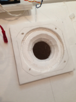
Here is a detail of the frustrum.
Here is a detail of the frustrum.
Attachments
That new sound clip is way better than the previous series  . But one thing I noticed, your entry points for the mids seem to be way further from the entry of the CD than on similar synergy horns.
Isn't the entry point distance determined by the crossover point used to keep things in phase? E.G. equal path distance for mids and CD?
Like this picture:
 from: http://www.diyaudio.com/forums/multi-way/244890-synergy-horns-dayton-prv.html
You'll see the mid entry points are almost at the beginning of the horn and the lower mid (3-way) are further out.
Is it because you ask the Vifa's to play a wider frequency range? How is the phase response in a solution like yours?
. But one thing I noticed, your entry points for the mids seem to be way further from the entry of the CD than on similar synergy horns.Isn't the entry point distance determined by the crossover point used to keep things in phase? E.G. equal path distance for mids and CD?
Like this picture:
You'll see the mid entry points are almost at the beginning of the horn and the lower mid (3-way) are further out.
Is it because you ask the Vifa's to play a wider frequency range? How is the phase response in a solution like yours?
Last edited:
Dr McClain,
Thanks. I put a resistor in series with the tweet and it tamed it down. A lot better now. The 4 Vifa's will give 91 dB or so and the tweeter is 95 dB so probably needed to be padded. If you want the dimensions download Bwaslo's spreadsheet v5 and input 90 deg x 90 deg for horn angle. Put 4 in for the distance of driver port location to get the dimensions for the HornResp calcs or AkAbak calcs. If using a 1 inch CD then dimensions as is work. If using a horn like PH44 then truncate the throat section until it matches. DIY Synergy/Unity spreadsheet there is a lot of good info on the Unity threads in the Multiway forum.
Thanks for the numbers, I'll get on it. I keep some 20 ohm 20 watts around just for that reason. Hefty resistors, yeah, but I favor piezos and they seem to need it.
I got to thinking, foam board makes great matrix for surface transducers (the "turn anything into a speaker" drivers). That being so, might the large surface area of these and the symmetry lend itself to some "box" resonances? In my little box with the square drivers, they were crammed together so there was more driver than foam board showing, but these might react differently.
If you think that might be a problem, I have a simple fix that I use on my larger PA cabs. I glue odd shaped pieces, mostly scrap of various materials, to the inside surfaces in random placements, covering maybe 10 to 20% of the surface. It doesn't prevent all box effect, but it breaks up major peaks. Then again, if it's occurring, it might even be a good thing in your case. Consider experimenting with it and collect your own data. I've had more than a couple of such experiments turn out with opposite results from what those well versed on theory but low on sawdust creation predicted.
Wesayso,
Yes, it was a compromise because I am trying to make a two way so this is really more of a bass driver that I am forcing to get higher freq. I have not looked at the phase mismatch with the HF yet. The simulations showed that at this location the bandwidth goes from 150 Hz to about 1300 Hz. Putting the ports near the throat would push this to a 385 Hz low end and then I would really need a 3 way. One thing I am seeing in working multiple drivers is the pain in making good cross over. I may have to go with a digital solution like miniDSP. It reminds me how great sounding a simple full range driver speaker is. You just can't get the high SPL levels that PA systems need.
Yes, it was a compromise because I am trying to make a two way so this is really more of a bass driver that I am forcing to get higher freq. I have not looked at the phase mismatch with the HF yet. The simulations showed that at this location the bandwidth goes from 150 Hz to about 1300 Hz. Putting the ports near the throat would push this to a 385 Hz low end and then I would really need a 3 way. One thing I am seeing in working multiple drivers is the pain in making good cross over. I may have to go with a digital solution like miniDSP. It reminds me how great sounding a simple full range driver speaker is. You just can't get the high SPL levels that PA systems need.
Last edited:
Doc McClain,
I plan to add some bracing as I do feel the panels vibrating. Especially the two walls that are not double thickness. I usually add lots of bracing on foam core projects - normally any span more than 3 or 4 inches gets a brace or a rib.
The foam core actually makes a great flat panel speaker when you attach those
voice coil transducers that turn any surface into a speaker. I have some of those and it is perhaps the simplest foam core speaker possible - a single flat sheet.
Wesayso,
Yes, it was a compromise because I am trying to make a two way so this is really more of a bass driver that I am forcing to get higher freq. I have not looked at the phase mismatch with the HF yet. The simulations showed that at this location the bandwidth goes from 150 Hz to about 1300 Hz. Putting the ports near the throat would push this to a 385 Hz low end and then I would really need a 3 way. One thing I am seeing in working multiple drivers is the pain in making good cross over. I may have to Ho with a digital solution like miniDSP.
I figured as much... if passive were easy, I'm already dreaming away thinking of a home synergy with 4 TC9's and a Vifa XT25 instead of a CD driver.
I think you might need some time alignment between mids and CD in this configuration? Or at least a longer path from the mids into the horn at that position I'd guess. Is the distance of the holes within the quarter wave length of the chosen crossover point?
Last edited:
Looking back through the thread I see many have already suggested the same or similar to what I've said, including the builder. My fault for not reading it all, but good in that it means we're all on the same page and probably correct in our assumptions.
I once suspended a full length mirror from the ceiling and stuck a couple transducers on the back. What a weird sensation, watching myself play guitar with the sound coming from the image in front of me.
The Vifas are flat out to 20k on axis (the off axis not being pertinent to a horn, I think). You might consider letting them dominate some higher freqs and xo up high. Maybe a low pass on them around 8 to10k and some well padded very high end tweeters. Like I said, I favor piezos. Cheap, easy to work with, and if their little plastic horns don't fit your design, the element in back is usually around 1" dia. Plus, they don't figure into network impedance. High pass them at the same higher freq that the Vifas are low passed, and they might not even need to be padded. Well, a dog might disagree, since a lot of piezos go up to 27k or so.
Hey, where you at in Virgina, xrk971? I'm in SWVA, near Bristol.
I figured as much... if passive were easy, I'm already dreaming away thinking of a home synergy with 4 TC9's and a Vifa XT25 instead of a CD driver.
I think you might need some time alignment between mids and CD in this configuration? Or at least a longer path from the mids into the horn at that position I'd guess. Is the distance of the holes within the quarter wave length of the chosen crossover point?
I have a design where a Vifa BC25 silk dome can work very well too - I just happened to have the PH44's already.
To tell you the truth, I am new to this Synergy business and have not thought about the XO freq and the 1/4-wave length of the horn. Since I did not consider that at all, I am sure it is not correct. My bass ports are located at a horn circumference of 83 cm and that corresponds to 103 Hz quarter wave. I think this is for making sure the port dia is much smaller than the wavelength affected by the port size.
The port is located about 6.5 in from the throat of the PH44 horn so the quarter wave freq is 518 Hz. So not sure if this means that I really should have it closer in at about 3.25 in from the throat?
Last edited:
Looking back through the thread I see many have already suggested the same or similar to what I've said, including the builder. My fault for not reading it all, but good in that it means we're all on the same page and probably correct in our assumptions.
I once suspended a full length mirror from the ceiling and stuck a couple transducers on the back. What a weird sensation, watching myself play guitar with the sound coming from the image in front of me.
The Vifas are flat out to 20k on axis (the off axis not being pertinent to a horn, I think). You might consider letting them dominate some higher freqs and xo up high. Maybe a low pass on them around 8 to10k and some well padded very high end tweeters. Like I said, I favor piezos. Cheap, easy to work with, and if their little plastic horns don't fit your design, the element in back is usually around 1" dia. Plus, they don't figure into network impedance. High pass them at the same higher freq that the Vifas are low passed, and they might not even need to be padded. Well, a dog might disagree, since a lot of piezos go up to 27k or so.
Hey, where you at in Virgina, xrk971? I'm in SWVA, near Bristol.
So along the lines of an all TC9FD single type full range driver, maybe we can mount the 4 Vifa's in sideways star config to form a 1 in duct which then leads to the throat of the horn. Let the Vifa's go from whatever the low cutoff is to their natural 20 kHz high end. I think the problems is, the HF's won't make it out since the Vifa design requires an open face for the HF's to radiate from the paper dustcap, if that is blocked may not work. It then goes back to the volume of the chamber being very small which is why CD's are the way they are. A closer approximation is to put 4 Vifa's open face in a 2x2 array and put that at the horn throat which contains the 4 drivers. At a distance far away, they will appear a single point source full range driver.
I live up in NoVa.


Like this picture:
from: http://www.diyaudio.com/forums/multi-way/244890-synergy-horns-dayton-prv.html
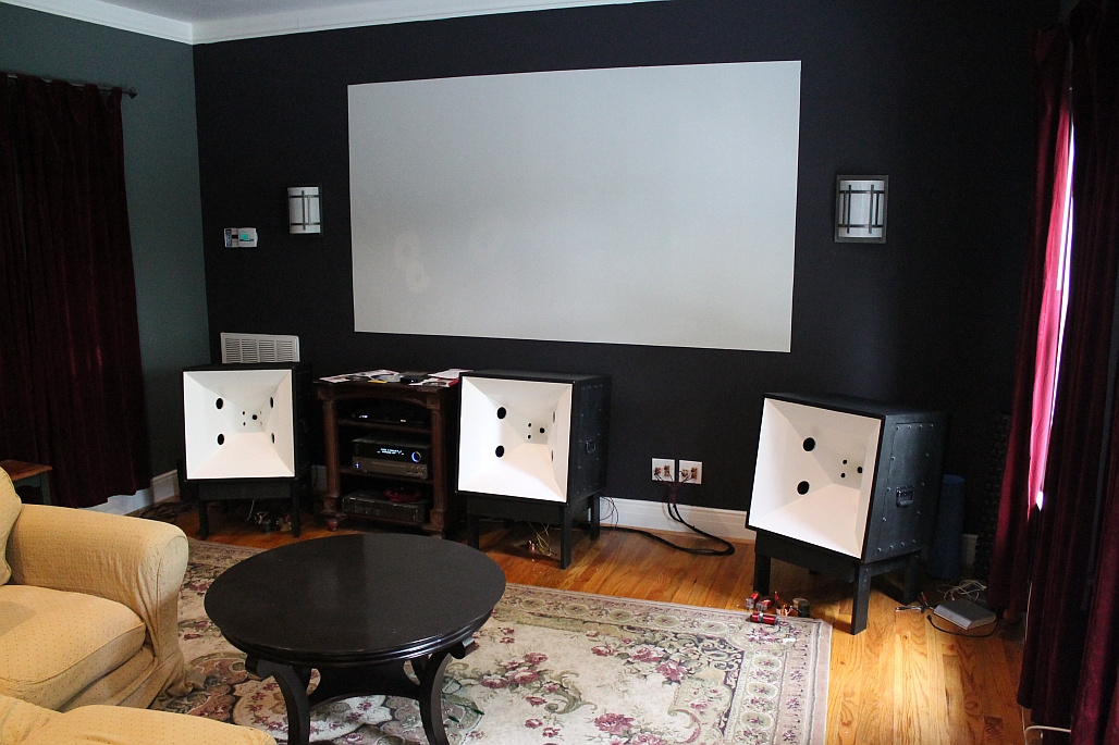
Impressive speakers! I like how the wall terminals are on display too!
So along the lines of an all TC9FD single type full range driver, maybe we can mount the 4 Vifa's in sideways star config to form a 1 in duct which then leads to the throat of the horn. Let the Vifa's go from whatever the low cutoff is to their natural 20 kHz high end. I think the problems is, the HF's won't make it out since the Vifa design requires an open face for the HF's to radiate from the paper dustcap, if that is blocked may not work. It then goes back to the volume of the chamber being very small which is why CD's are the way they are. A closer approximation is to put 4 Vifa's open face in a 2x2 array and put that at the horn throat which contains the 4 drivers. At a distance far away, they will appear a single point source full range driver.
I live up in NoVa.
I think that sounds like a reasonable adjustment to the design. The loss of "sparkle" you mention elsewhere is likely due to having them try to reproduce low freq at the same time. That sucks up a lot of energy, and the reproduction of the low freqs precludes accurate reproduction of the highs. Perhaps use a small woofer or two (I think subs might be a bit much for the substructure in terms of weight and box vibration) Give them the low freq and let the Vifas handle everything above. I've favored the Sony "Dynamic Bass" poly cone neo mags (Parts Express # 299-011). I built a 2.1 PA with 48 of them (a Sweet 16 center and two 2x6 towers, plus a couple subs and 4 piezos). Marvelous little drivers. They've sold out, in part thanks to me. I'd be glad to donate a couple to the project for testing.
As for the problem with the 1" opening for the Vifas, consider cutting them a full sized opening then placing a Karlson style bilateral parabolic vent over them. It'll focus the freqs in the way the horn expects. I can calculate the proper shape for you, given the size of the opening and the angle of the driver to axis. They can be simply taped in place for testing.
Doc McClain,
I have thought about a Karlson type aperture too for the little driver injection holes. Although over a 3 in length the frequencies we are dealing with are pretty high to be impacted kind of like a K tube tweeter - also, if you orient the apex of the K aperture towards the horn throat, it may have some Beneficial effects for shielding the CD tweeter wavefront from an abrupt change in geometry. I have had some success modeling the K aperture by approximatig it as a series of variable rectangular aperture radiators in feont of a waveguide for large scales in the bass region like a K15 or Karlsonator.
I have thought about a Karlson type aperture too for the little driver injection holes. Although over a 3 in length the frequencies we are dealing with are pretty high to be impacted kind of like a K tube tweeter - also, if you orient the apex of the K aperture towards the horn throat, it may have some Beneficial effects for shielding the CD tweeter wavefront from an abrupt change in geometry. I have had some success modeling the K aperture by approximatig it as a series of variable rectangular aperture radiators in feont of a waveguide for large scales in the bass region like a K15 or Karlsonator.
I suspect you're right, the high freqs need as much length on the vent as possible. The usual ratio is 5.33 x aperture diameter. It'd take a K-tube to do the job, and that would really mess up your geometry. I've experimented with a 4 point star shaped K type aperture (two K vents, wide ends together) that might fit but that would give a wide dispersion on the high freqs, some towards the throat but some out the front. Good for imaging (stereo and/or depth) but I'm not so sure it'd have that effect on the tweeter wave.
- Home
- Loudspeakers
- Full Range
- Foam Core Board Speaker Enclosures?