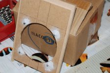
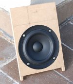
I've only listened to it in it's cardboard packing box (so far from optimal) but it sounded very good just like that. Very natural on vocals, no harshness that I could detect for the short time I listened.
A very quick update. I did manage to get the power tools out for a short while this afternoon, but only managed to cut the top and bottom pieces. I've not yet done any of the rebating. Although I was hoping this project would be more like my p2p gainclone (which I finished in record time) it is starting to shape up to being more like my MTM's (which took about seven years)
From next weekend there is going to be a lot of time spent on preparing the new house for moving in, so unfortunately progress is probably going to be slow for a while. The upside is that the new place has a double garage so I have somewhere I can work and leave the tools out (currently I have to work on the balcony).
Tony.
Well I finally got some time to do some woodworking today. Unfortunately not enough to get the first box done though. I have no idea where my circle jig is so I'm probably going to have to make a new one
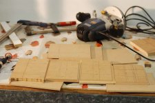
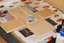
I managed to do the rebating of the top bottom and rear baffle, and got the sides cut. I still have to do the front baffle rebates and speaker cutouts, and the very shallow rebates for the port baffle, and cut the port baffles themselves. But I guess progress is progress
Hopefully I will be able to get a few hours every now and then to get them finished. We bought a new house shortly after I started this project and that has been where all of the time has been going.
anyway a couple of pics. One showing the bits and the other showing the box mocked up. The rear baffle is not fitting exactly because the front one hasn't had it's 3mm rebate cut.
edit: Its slow going with just a router a jigsaw and a straight bit of MDF (for use as a fence) at your disposal. I'm sure it would be a LOT quicker if I had a router table
Tony.
Attachments
Last edited:
Well wonders never cease and I had quite a bit of time today to continue on All panels completed for one box, and all routing done except for the speaker cutout.
I had another look for my circle jig, but couldn't find it, so it looks like the next thing to do is to make a new one.
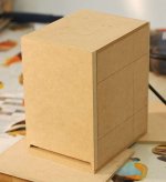
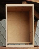
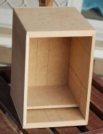
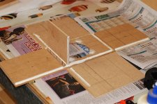
Pictures of the enclosure just sitting together, no glue as yet. The fit is not too bad. Had one slight problem with the port slot in the first side, was about 1mm too low, re-routed to have a loose fit on that side and adjusted the other. Also the rear baffle for some reason seems about 2mm too much on the rebate, I suspect the sides are slightly longer than they were supposed to be. Shouldn't be a problem once glued together though I may trim them down a small bit.
The 4 1/2 year old (who is now 5) is happy that some progress has been made. She said to me last night I had to keep working on it all night to get it finished She also recently said when I said something was going to take a while, "I hope that isn't going to take as long as my speakers, that will be forever"....
Tony.
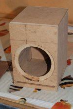
All panels completed for one box, and all routing done except for the speaker cutout. I had another look for my circle jig, but couldn't find it, so it looks like the next thing to do is to make a new one.
Pictures of the enclosure just sitting together, no glue as yet. The fit is not too bad. Had one slight problem with the port slot in the first side, was about 1mm too low, re-routed to have a loose fit on that side and adjusted the other. Also the rear baffle for some reason seems about 2mm too much on the rebate, I suspect the sides are slightly longer than they were supposed to be. Shouldn't be a problem once glued together though I may trim them down a small bit.
The 4 1/2 year old (who is now 5) is happy that some progress has been made. She said to me last night I had to keep working on it all night to get it finished
She also recently said when I said something was going to take a while, "I hope that isn't going to take as long as my speakers, that will be forever".... Tony.
Attachments
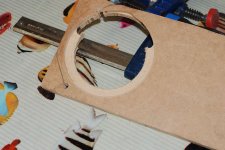
OK So I made the circle jig yesterday, finished it about 8:30PM and had to clean up so didn't get a chance to test it until tonight (went back to work today).
Apart from operator stupidity* it worked well
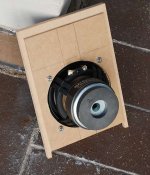
Pics attached of the circle jig, the hole (demonstrating the operator stupidity*) and the speaker sitting in said hole.
It looks like I need to set the depth a little bit deeper for the rebate probably another 1mm, but the cutout size is perfect, both for the outer and the inner
I created a thread for the making of the circle jig here --> http://www.diyaudio.com/forums/equipment-tools/226853-diy-circle-jig.html . I probably should have done it as a blog post, but i'ts done now
*operator stupidity consisted of me carefully setting the depth of the cut to 6.5mm releasing the plunge lock, and then proceeding to removed the depth gauge from the router (which has been necessary when trimming the edges due to it fouling my fence). I then started to cut the outer rebate but thought that the router seemed to be going very deep. I stopped and checked and realized my stupidity. I reset the depth and this time left the depth gauge connected and did the rest of the hole at the specified depth Glad I was using a scrap bit of mdf for test purposes!
Tony.
Apart from operator stupidity* it worked well
Pics attached of the circle jig, the hole (demonstrating the operator stupidity*) and the speaker sitting in said hole.
It looks like I need to set the depth a little bit deeper for the rebate probably another 1mm, but the cutout size is perfect, both for the outer and the inner
I created a thread for the making of the circle jig here --> http://www.diyaudio.com/forums/equipment-tools/226853-diy-circle-jig.html . I probably should have done it as a blog post, but i'ts done now
*operator stupidity consisted of me carefully setting the depth of the cut to 6.5mm releasing the plunge lock, and then proceeding to removed the depth gauge from the router (which has been necessary when trimming the edges due to it fouling my fence). I then started to cut the outer rebate but thought that the router seemed to be going very deep. I stopped and checked and realized my stupidity. I reset the depth and this time left the depth gauge connected and did the rest of the hole at the specified depth
Glad I was using a scrap bit of mdf for test purposes! Tony.
Attachments
So I have made a bit more progress today I've cut the hole in the front baffle for the driver for the fist box.
Now I have realised that I'm not sure what I am going to use to mount the driver, and that what I do decide on is going to have to go on the back of the baffle rather than be set into it, as there is only around 5mm thickness to work with I probably should have gone with a 16mm thick baffle. Oh well. I'll probably just epoxy some nuts onto the back after screwing in the bolts.
Also I remeasured and it looks like the problem is not with the sides being too long but with my rear baffle being 1mm too short. Stuffed up somewhere there. Not a big drama though the glue should hopefully fill it.
Tony.
I've cut the hole in the front baffle for the driver for the fist box. Now I have realised that I'm not sure what I am going to use to mount the driver, and that what I do decide on is going to have to go on the back of the baffle rather than be set into it, as there is only around 5mm thickness to work with
I probably should have gone with a 16mm thick baffle. Oh well. I'll probably just epoxy some nuts onto the back after screwing in the bolts. Also I remeasured and it looks like the problem is not with the sides being too long but with my rear baffle being 1mm too short. Stuffed up somewhere there. Not a big drama though the glue should hopefully fill it.
Tony.
Attachments
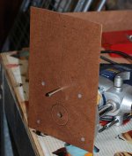
I made another small advancement today. If I keep making small steps they might actually be finished! (I also find that posting helps motivate me to keep making progress)
I found some M4 caphead screws, that I had salvaged from a Fujitsu Mainframe that we decommed in the early 90's. I knew they would come in handy for something sometime I drilled the holes for the screws and checked that they lined up ok. When I was happy that they fit I took the speaker back out, and put the screws in, and used some kneadable epoxy to epoxy the nuts in place (after roughing up the MDF with a wood rasp to make sure the epoxy had something to grab on to).
Hopefully since these won't need a lot of torque it should be enough to hold the nuts in place.
Now all I need to do is find the terminals that I know are in a box somewhere, and install them in the rear baffle and start gluing!
Tony.
I found some M4 caphead screws, that I had salvaged from a Fujitsu Mainframe that we decommed in the early 90's. I knew they would come in handy for something sometime
I drilled the holes for the screws and checked that they lined up ok. When I was happy that they fit I took the speaker back out, and put the screws in, and used some kneadable epoxy to epoxy the nuts in place (after roughing up the MDF with a wood rasp to make sure the epoxy had something to grab on to). Hopefully since these won't need a lot of torque it should be enough to hold the nuts in place.
Now all I need to do is find the terminals that I know are in a box somewhere, and install them in the rear baffle and start gluing!
Tony.
Attachments
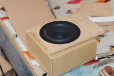
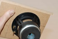
Yes they have a very nice basket The thin baffle helps a lot though. I probably should have gone with the 16mm MDF for the front. The depth of the rebate is 7mm which only leaves 5mm thickness for the driver to mount through, which is a bit thin.
Certainly doesn't need any chamfering of the backside of the hole though
Tony.
The thin baffle helps a lot though. I probably should have gone with the 16mm MDF for the front. The depth of the rebate is 7mm which only leaves 5mm thickness for the driver to mount through, which is a bit thin. Certainly doesn't need any chamfering of the backside of the hole though
Tony.
OK A little more progress on the worlds slowest speaker build
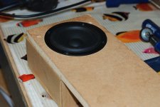
I've glued the top, bottom, sides and front baffle today. Drying as I type. I'm yet to find the speaker terminals that I'm going to use (some fairly ordinary ones from futurelec I bought before but decided weren't good enough form my MTM's).
Once I've found those I should be able to do the rear baffle as well and can do a listening test to one speaker, and possibly some objective measurements (new house and not sure whether the study where the computer is is suitable for measurements).
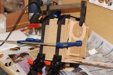
Anyway here are the obligatory pictures. The bit of mdf sticking out the port was there to ensure that the port baffle was in the right place since I mucked up the rebate on one of the sides.
Tony.
I've glued the top, bottom, sides and front baffle today. Drying as I type. I'm yet to find the speaker terminals that I'm going to use (some fairly ordinary ones from futurelec I bought before but decided weren't good enough form my MTM's).
Once I've found those I should be able to do the rear baffle as well and can do a listening test to one speaker, and possibly some objective measurements (new house and not sure whether the study where the computer is is suitable for measurements).
Anyway here are the obligatory pictures. The bit of mdf sticking out the port was there to ensure that the port baffle was in the right place since I mucked up the rebate on one of the sides.
Tony.
Attachments
the worlds slowest speaker build
You'll need to stretch it out another have decade -- at least
dave
yeah these are actually going pretty fast by my standards I joined here back in August 2003 to ask some questions about the speakers I was thinking about building. I finally "finished" them in Oct 2011. I put finished in quotes because I never got around to getting the felt that I wanted to put on the baffles or the proper covers that was to integrate with the felt
I've just taken the clamps off but I think I really need a brace between the sides. The 6mm mdf is pretty hollow sounding which I was expecting. I've got some small diameter dowel around here somewhere if I can dig it up. I did find the speaker terminals which is good. Top and bottom sound good on a rap test.
Tony.
I joined here back in August 2003 to ask some questions about the speakers I was thinking about building. I finally "finished" them in Oct 2011. I put finished in quotes because I never got around to getting the felt that I wanted to put on the baffles or the proper covers that was to integrate with the felt I've just taken the clamps off but I think I really need a brace between the sides. The 6mm mdf is pretty hollow sounding which I was expecting. I've got some small diameter dowel around here somewhere if I can dig it up. I did find the speaker terminals which is good. Top and bottom sound good on a rap test.
Tony.
I couldn't resist. I had to clamp the back on and hook up the driver with alligator clips and have a listen. Originally I was going to do some impedance measurements to check that the two pieces of dowel I put in were not causing any problems, but I didn't get that far
What can I say... This project is definitely worth finishing!! The speaker sounds a bit unbalanced, but that is to be expected as I have no Baffle Step compensation at this stage, however the vocals on Ella and Louis sounded VERY good indeed. apart from the slightly more pronounce midrange and treble they sound very close to my MTM's. In fact I had one of the MTM's playing with the little SB on top of the other replacing it, and the image stayed dead centre and it was not perceptible that there was anything different to normal! I think that the sensitivity of my MTM's must be pretty much the same as these little speakers (which means that the mtm's are a tad less efficient than I thought).
The only other thing was that I could notice a slight tizziness in the top end, which is probably the breakup, but it was not at all bad. I'll wait till I've done some measurements (and played with BSC) before trying to do anything about that though.
For a set of computer speakers for my 5YO these are going to be very very good indeed!
Tony.
OK first measurement Bear in mind that this is just with the rear baffle being held in place by a single F clamp and not properly sealed. The other thing to bear in mind is that this is a completely bare box. No lining of any sort just bare MDF. It looks from the impedance curve that the tuning is pretty close to my target of 70Hz.
I'll take out the braces I added and measure again and see if the twitches in the impedance curve at just over 1 and 1.5Khz are being caused by the braces. Apart from another small glitch at around 9.5K which probably corresponds with the breakup on the manufacturers curves the impedance plot I think it looks very good indeed
Tony.
Bear in mind that this is just with the rear baffle being held in place by a single F clamp and not properly sealed. The other thing to bear in mind is that this is a completely bare box. No lining of any sort just bare MDF. It looks from the impedance curve that the tuning is pretty close to my target of 70Hz. I'll take out the braces I added and measure again and see if the twitches in the impedance curve at just over 1 and 1.5Khz are being caused by the braces. Apart from another small glitch at around 9.5K which probably corresponds with the breakup on the manufacturers curves the impedance plot I think it looks very good indeed
Tony.
Attachments
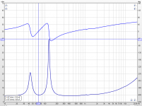
Well it looks like the giltches are not the bracing, but by a kind twist of fate I must have over compensated for the volume slightly, and with the bracing (which I hadn't originally allowed for) in place the volume is just about perfect for the 70Hz tuning frequency. Without it it is about 2.5 hz lower.
I'm actually thinking that the sharp glitch at just above 1Khz might be the F clamp, as no doubt the position of it on the front baffle moved a bit from the first measurement, and coincidentally the glitch moved a bit as well.
Tony.
I'm actually thinking that the sharp glitch at just above 1Khz might be the F clamp, as no doubt the position of it on the front baffle moved a bit from the first measurement, and coincidentally the glitch moved a bit as well.
Tony.
Attachments
the sharp glitch at just above 1Khz
It is about the right frequency to be the transition from pistonic behaviour to resonant behaviour.
dave
ok thanks Dave. in all it is a pretty small gitch I think. I'm not too worried about it at the moment.
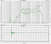
I've just tried doing some accoustic measurements and well given the setup I don't think I should read too much into them, but they aren't particularly good. I'm in a 3 X 4M room with furniture everywhere and the speaker sitting on the shelf of my desk. I tried doing nearfield, but I'll have to try slpicing the port and woofer measurements together. It certainly doesn't look like I expected though.. big rise (like almost 10db) around 125Hz. box is not properly sealed so that may have something to do with it I guess, or perhaps I have damaged my mic again
It might be a while before I get some proper measurements, but I think I should at least finish the box before doing that Measurement shown was taken at about 50cm and is 1/8th octave smoothed. It looks like what I was hearing as needing correcting in the top end was correct too.
Tony.
I've just tried doing some accoustic measurements and well given the setup I don't think I should read too much into them, but they aren't particularly good. I'm in a 3 X 4M room with furniture everywhere and the speaker sitting on the shelf of my desk. I tried doing nearfield, but I'll have to try slpicing the port and woofer measurements together. It certainly doesn't look like I expected though.. big rise (like almost 10db) around 125Hz. box is not properly sealed so that may have something to do with it I guess, or perhaps I have damaged my mic again
It might be a while before I get some proper measurements, but I think I should at least finish the box before doing that
Measurement shown was taken at about 50cm and is 1/8th octave smoothed. It looks like what I was hearing as needing correcting in the top end was correct too. Tony.
Attachments
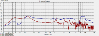
The rise at 125Hz is too steep to be the box tuning, as your letting in some of the room, it is likely to be that. The measurements do show a gradual decline below 1k, most likely due to bafflestep and then a small rise in the top end, which may not need addressing as it will most likely vanish off axis.
My only concern is that your daughter, with the young ears, may find them dull sounding, it might be unlikely that she notices though.
My only concern is that your daughter, with the young ears, may find them dull sounding, it might be unlikely that she notices though.
I'm a bit perplexed about the resuilt actually. I did a 1cm nearfield measurement and it also has a big (much bigger than in the 50cm measurement) sharp hump at 125Hz. It does look way too steep to be the box tuning, and is absolutely nothing like the modeled response. having another look at the impeadance curve the second (very high) spike is at pretty much 125Hz.
Leaks or not there shouldn't be this sort of effect. It may be a case of the driver behaving very different to when modeled, or I may have really screwed something up Funny thing is I didn't notice it at all when listening (though I may now).
Tony.
Leaks or not there shouldn't be this sort of effect. It may be a case of the driver behaving very different to when modeled, or I may have really screwed something up
Funny thing is I didn't notice it at all when listening (though I may now). Tony.
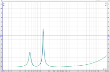
Hear are the nearfield measurements I took last night. taken at around 5mm Blue is the driver red is the port. One thing that I think this shows is that the little glitch in the impedance curve just above 1Khz is actually the port resonance
I've never done a slot port before, so I don't know whether my moddeling using a standard round port (as unibox doesn't have an option for rectangular ports) will have thrown things off completely.
Interestingly if I increase the series resistance from the modeled 0.2ohms to four ohms I start to get a pronounced hump around 125Hz. If I increase it to 10 ohms I get an almost perfect match for the woofer nearfield measurement. Perhaps I need to retry with proper wiring rather than alligator clips
Tony.
Attachments
- Status
- This old topic is closed. If you want to reopen this topic, contact a moderator using the "Report Post" button.
- Home
- Loudspeakers
- Full Range
- SB acoustics SB12MNRX25-4 "full range" Build thread