Hello diyaudio! I've been browsing these forums (Full Range in particular) for almost two years now, and I believe it's about time I give a loudspeaker build a try. I decided to start small (physically) and design a pair of ported full range loudspeakers to be used relatively near-field for music, as computer desktop speakers.
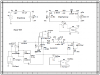
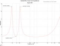
This past semester I took an Audio Engineering class taught around Dr. Leach's "Intro to Electroacoustics & Audio Amplifier Design", so my design is based off of these theories. I chose to design around the Alpair 6M because of its favorable QTS, resulting in a 4th order Butterworth roll-off on the lower frequencies. Attached are a mathcad file for calculations, the simulation circuit, and two plots of voice coil impedance and port+diaphram on-axis pressure (if interested).
Introduction aside, here are the highlights of the design:
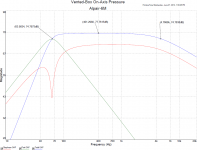
Now to my concern. The on-axis SPL plot from my simulation shows an upper -3db around 4.7kHz. This obviously seems very unfavorable for a full range design. To any Alpair 6M owners out there, does this drop-off appear to by a flaw in my simulation, or is it to be expected from my design? If the latter, how could I fix this problem? Thanks in advance!
This past semester I took an Audio Engineering class taught around Dr. Leach's "Intro to Electroacoustics & Audio Amplifier Design", so my design is based off of these theories. I chose to design around the Alpair 6M because of its favorable QTS, resulting in a 4th order Butterworth roll-off on the lower frequencies. Attached are a mathcad file for calculations, the simulation circuit, and two plots of voice coil impedance and port+diaphram on-axis pressure (if interested).
Introduction aside, here are the highlights of the design:
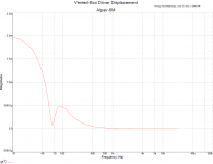
- Helmholtz Resonance Freq = 63 Hz (same as fS and lower cutoff)
- Port dimensions = 2.5cm diameter, 7.1cm length (cylindrical)
- Inner box dimensions = 16.1cm depth, 9.6cm width, 25.7cm height
Now to my concern. The on-axis SPL plot from my simulation shows an upper -3db around 4.7kHz. This obviously seems very unfavorable for a full range design. To any Alpair 6M owners out there, does this drop-off appear to by a flaw in my simulation, or is it to be expected from my design? If the latter, how could I fix this problem? Thanks in advance!
Attachments
Looking at the FR curve of the 6P would suggest that your simulation is perhaps. . . not optimal.
I suspect that theory and textbook has gotten in the way of reality in this case. There are several free box simulation programs that you could use to check your model, or just use. The predictions from these programs, when properly applied, compare well to measured results.
I suspect that theory and textbook has gotten in the way of reality in this case. There are several free box simulation programs that you could use to check your model, or just use. The predictions from these programs, when properly applied, compare well to measured results.
Hello diyaudio! I've been browsing these forums (Full Range in particular) for almost two years now, and I believe it's about time I give a loudspeaker build a try. I decided to start small (physically) and design a pair of ported full range loudspeakers to be used relatively near-field for music, as computer desktop speakers.
This past semester I took an Audio Engineering class taught around Dr. Leach's "Intro to Electroacoustics & Audio Amplifier Design", so my design is based off of these theories. I chose to design around the Alpair 6M because of its favorable QTS, resulting in a 4th order Butterworth roll-off on the lower frequencies. Attached are a mathcad file for calculations, the simulation circuit, and two plots of voice coil impedance and port+diaphram on-axis pressure (if interested).
Introduction aside, here are the highlights of the design:
- Helmholtz Resonance Freq = 63 Hz (same as fS and lower cutoff)
- Port dimensions = 2.5cm diameter, 7.1cm length (cylindrical)
- Inner box dimensions = 16.1cm depth, 9.6cm width, 25.7cm height
Now to my concern. The on-axis SPL plot from my simulation shows an upper -3db around 4.7kHz. This obviously seems very unfavorable for a full range design. To any Alpair 6M owners out there, does this drop-off appear to by a flaw in my simulation, or is it to be expected from my design? If the latter, how could I fix this problem? Thanks in advance!
Usually box sims aren't much good above 500 Hz.
And if they were, at some stage you would need to convolve the driver's actual FR with the sim.
My actual experienceis that the A6m is a bit tipped up sounding at the top.
Here is my sim of your box.
dave
And if they were, at some stage you would need to convolve the driver's actual FR with the sim.
My actual experienceis that the A6m is a bit tipped up sounding at the top.
Here is my sim of your box.
dave
Attachments
And just to point out, a flat alignment usually isn't ideal in practical conditions since room-gain is likely to substantially increase LF gain. That said, if I do a generic design for the forums, I admit I usually provide a similar alignment since it's the optimal baseline, but it's on the understanding that people will need to adjust the box tuning to suit their particular room / system / taste.
Thank you for the replies, everyone. I did not know about the ineffectiveness of models like mine at high frequencies. I guess it's good to hear that I'm not too far off from getting it.
Thanks for the simulation, Dave! It appears that my results don't vary too drastically from the ones you provided, which is reassuring.
Thanks for the insight. This being my first build, I don't have much experience with room-gain. For that reason, I chose to start with an ideally "maximally flat" low-frequency response in order to try and better understand the effects of a room. I'll definitely keep the port tunable for testing before sealing it up.
Here is my sim of your box.
dave
Thanks for the simulation, Dave! It appears that my results don't vary too drastically from the ones you provided, which is reassuring.
And just to point out, a flat alignment usually isn't ideal in practical conditions since room-gain is likely to substantially increase LF gain. That said, if I do a generic design for the forums, I admit I usually provide a similar alignment since it's the optimal baseline, but it's on the understanding that people will need to adjust the box tuning to suit their particular room / system / taste.
Thanks for the insight. This being my first build, I don't have much experience with room-gain. For that reason, I chose to start with an ideally "maximally flat" low-frequency response in order to try and better understand the effects of a room. I'll definitely keep the port tunable for testing before sealing it up.
Last edited:
A model of the loudspeaker & box.
dave
Ah, I see now. Thx.
- Status
- This old topic is closed. If you want to reopen this topic, contact a moderator using the "Report Post" button.
- Home
- Loudspeakers
- Full Range
- Markaudio Alpair 6M Vented Box Enclosure - High Frequency Concern