I wonder what was the rationale behind the original F-81. It was designed for the old FE83/FE83E, which had Fs~140Hz IIRC. It was a ~12ft pipe.
Essentially, Nagaoka was aiming for 1/2 wave of the lowest fundamental of double-bass, more or less (it's technically a horn, albeit only just), and to provide a very low 1/4 wave fundamental for HT use in compact spaces. That's about it as far as rationale goes. Technical performance is appalling, but you need to escape from the Western mind-set in order to understand what he was up to. In Japan, a flat FR isn't often a matter of much interest to those who like small wideband drivers.
Last edited:
Essentially, Nagaoka was aiming for 1/2 wave of the lowest fundamental of double-bass, more or less (it's technically a horn, albeit only just), and to provide a very low 1/4 wave fundamental for HT use in compact spaces. That's about it as far as rationale goes. Technical performance is appalling, but you need to escape from the Western mind-set in order to understand what he was up to. In Japan, a flat FR isn't often a matter of much interest to those who like small wideband drivers.
Ok, thanks for the explanation. So it was based on musical content more than electro-acoustical parameters. Will a super-low ¼-wave fundamental really help the tiny driver, assuming content goes that low? That would be ~23hz for the F-81 and ~38hz for my somewhat T/S-based FF85WK simulacrum.
IG
Thanks for undertaking this again. If it's not too much of a hassle, can you compare Z=0 to Z=1/5 down the line? I would try to snipe the 5/4 mode this way, since the diaphragm is small and the line quite long, and try de-Q holes for killing 7/4 and 9/4 modes. Here are the Z offsets for de-Q holes for each mode:
7/4-mode:
32cm
96cm
160cm
9/4-mode:
24.89cm
74.67cm
124.45cm
174.23cm
IG
The model of this is in new thread here http://www.diyaudio.com/forums/full-range/237384-flute-pipe-tl.html#post3520890
Ok, thanks for the explanation. So it was based on musical content more than electro-acoustical parameters. Will a super-low ¼-wave fundamental really help the tiny driver, assuming content goes that low? That would be ~23hz for the F-81 and ~38hz for my somewhat T/S-based FF85WK simulacrum.
See my previous post. Technical performance of the F-81 is appalling in terms of FR (it does get somewhat better rammed near boundary conditions, though these things are relative), excursion etc. & you need to watch internal reflections coming back through the cone too.
In essence, no, it doesn't. Not by most conventional Western standards anyway: tuning a tiny driver so low is really asking for it; 0.707Fs is typically about the limit. There are certain exceptions with full sized, uncompromised horns where you technically can get down to Flc (-3dB corner from suspension compliance), but these come with major caveats, not least of which being size. But as I say, many fans of small wideband drivers in Japan have a very different approach to audio reproduction, and the F-81 does reflect this. I don't have a copy of the old (long out of print) Fostex Craft Handbook where it was originally published; as I recall all of the designs had FR charts smoothed 1/3 octave, so if you can find the appropriate edition for sale, you'll get an idea of what they were accepting themselves. A smooth FR was not one of the priorities however.
I agree the freq response of the F-81 in its stock form looks very bad in the simulation. But as I have seen, adding a few strategically placed d-Q'ing tuning holes helps. But you end up with something that is still very long but has performance of a well designed shorter TL.
Rather less than that, depending on how many holes & their size are drilled in it (I do actually know what I'm talking about you know). They may help depending on exactly what is done. But the box concept is fundamentally flawed by 'regular' technical standards. We should however recall that it wasn't designed with these in mind, but with other priorities. YMMV on whether you accept this approach or not. Some love it; it goes down well in Japan, so YMMV as ever.
It is interesting and fun to let go of the purely technical approach to design, though I'm still learning much about it. ") Here's a tiny recap of my F-81 FC likeness and the measurements which I don't believe I had posted here yet.
Here's a tiny recap of my F-81 FC likeness and the measurements which I don't believe I had posted here yet.
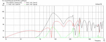
Blue trace = Driver output at 2"
Green trace = Vent output at ~2-3", with the cab's back to the wall, so effectively ~1/8 space from the mic's point of view
Far-field response:
Response at 60":
IG
Here's a tiny recap of my F-81 FC likeness and the measurements which I don't believe I had posted here yet.An externally hosted image should be here but it was not working when we last tested it.
An externally hosted image should be here but it was not working when we last tested it.
Blue trace = Driver output at 2"
Green trace = Vent output at ~2-3", with the cab's back to the wall, so effectively ~1/8 space from the mic's point of view
An externally hosted image should be here but it was not working when we last tested it.
Far-field response:
An externally hosted image should be here but it was not working when we last tested it.
Response at 60":
An externally hosted image should be here but it was not working when we last tested it.
IG
IG,
The response at 60 inches is a lot better than I imagined it could look. The bass extension seems to only go to 75 Hz in this case - the 40 Hz vent output seems to have disapperared. So you threw this away in the trash after you were done with it? Kind of a waste... would have made a good starting point for drilling holes to make the Flute Pipe TL.
The response at 60 inches is a lot better than I imagined it could look. The bass extension seems to only go to 75 Hz in this case - the 40 Hz vent output seems to have disapperared. So you threw this away in the trash after you were done with it? Kind of a waste... would have made a good starting point for drilling holes to make the Flute Pipe TL.
it would be nice to have a way to set the response of a regular Karlson Ultra-Fidelity enclosure type to limit peaking with a given driver -- IG81 do you think a BP sim set for certain Q is reliable enough to forge ahead or will front chamber height play a significant role? -- for a new thread think about how the front chamber should look including any reflector.
AkAbak sim of 1955 K15 Speaker
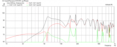
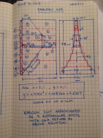
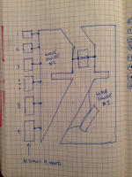
I put together a model of the original 1955 John Karlson K15 (vented no slots) http://home.planet.nl/~ulfman/images/Plans/original.gif. I modeled the back chamber as a waveguide of varying cross sectional area prescribed by the plan (see drawings below). I modeled the front chamber as a waveguide of varying cross sectional area as well but with a series of 9 rectangular ports with CSA prescribed by a quadratic function that describes the K-slot. The two waveguides are connected by a common vent (the 165 mm x 85 mm wide port). The driver is an Eminence Kappa Pro 12A (http://www.eminence.com/pdf/Kappa_Pro_12A.pdf). Measurements are at 3 meters away with speaker set on stand so that driver centerline is 24 in above floor and wall is 5 ft back. Even at 3 meters away, the SPL is 90 dB at 1 watt.
The curve fit of the K-slot is quite accurate when I compared it to the prescribed numbers. The fit is given by Y=0.974X^2+0.00874X+0.0207. This is for X=0,1 and Y=0,1. Simply scale function for any slot based on max height and width at Y(X=1).
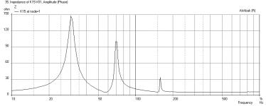
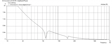
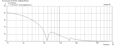
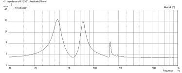
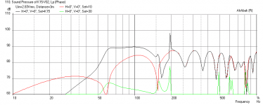
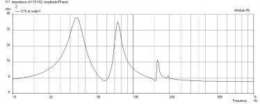
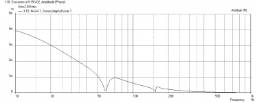
The frequency response shows a very strong bass response down to 60 Hz where it starts to decrease but has a decent SPL at 50 Hz. This is a very efficient speaker (the Eminence provides this). There are several dips and peaks as the frequency goes higher. I see a peculiar looking "W" shape from 150 to 200 Hz. Also shown are the impedance and cone displacement curves.
For anyone familiar with Karlson speaker measurements, does this look anything like it is supposed to? I may be completely missing the crucial points by modeling it as two waveguides connected by a vent with a leaky front waveguide. I think I may be missing something because this driver has an fs of 37 Hz and I am only getting 60 Hz peak.
By far, this was the most difficult and complex model I have done to date in AkAbak. It used about 30 nodes total.
This model has a universal scaling constant that will allow me to resize it en masse to shrink the cabinet and pop in a smaller driver. That immediately will impact the lower tuning freq as it depends on the path length.
I put together a model of the original 1955 John Karlson K15 (vented no slots) http://home.planet.nl/~ulfman/images/Plans/original.gif. I modeled the back chamber as a waveguide of varying cross sectional area prescribed by the plan (see drawings below). I modeled the front chamber as a waveguide of varying cross sectional area as well but with a series of 9 rectangular ports with CSA prescribed by a quadratic function that describes the K-slot. The two waveguides are connected by a common vent (the 165 mm x 85 mm wide port). The driver is an Eminence Kappa Pro 12A (http://www.eminence.com/pdf/Kappa_Pro_12A.pdf). Measurements are at 3 meters away with speaker set on stand so that driver centerline is 24 in above floor and wall is 5 ft back. Even at 3 meters away, the SPL is 90 dB at 1 watt.
The curve fit of the K-slot is quite accurate when I compared it to the prescribed numbers. The fit is given by Y=0.974X^2+0.00874X+0.0207. This is for X=0,1 and Y=0,1. Simply scale function for any slot based on max height and width at Y(X=1).
The frequency response shows a very strong bass response down to 60 Hz where it starts to decrease but has a decent SPL at 50 Hz. This is a very efficient speaker (the Eminence provides this). There are several dips and peaks as the frequency goes higher. I see a peculiar looking "W" shape from 150 to 200 Hz. Also shown are the impedance and cone displacement curves.
For anyone familiar with Karlson speaker measurements, does this look anything like it is supposed to? I may be completely missing the crucial points by modeling it as two waveguides connected by a vent with a leaky front waveguide. I think I may be missing something because this driver has an fs of 37 Hz and I am only getting 60 Hz peak.
By far, this was the most difficult and complex model I have done to date in AkAbak. It used about 30 nodes total.
This model has a universal scaling constant that will allow me to resize it en masse to shrink the cabinet and pop in a smaller driver. That immediately will impact the lower tuning freq as it depends on the path length.
Attachments
Last edited:
K15 with Betsy-K
I tried putting a Betsy K driver in the K15 box (full size box) and the sim results are surprisingly good - I would say better looking than the more expensive Kappa 12A. In particular, the impedance doesn't go into a wild high value.
I tried putting a Betsy K driver in the K15 box (full size box) and the sim results are surprisingly good - I would say better looking than the more expensive Kappa 12A. In particular, the impedance doesn't go into a wild high value.
Attachments
Fringy,
Hope you are ok with the weather not being like a monsoon or something. The K15 scales terribly the moment you shrink it as the tuning freq goes up very high and you get no bass when scaled to a 10 in box the freq is 100 Hz. I think I need a two dimensional scale so that length can be preserved while width is reduced to accommodate driver size and volume.
Hope you are ok with the weather not being like a monsoon or something. The K15 scales terribly the moment you shrink it as the tuning freq goes up very high and you get no bass when scaled to a 10 in box the freq is 100 Hz. I think I need a two dimensional scale so that length can be preserved while width is reduced to accommodate driver size and volume.
K15 with FF225WK
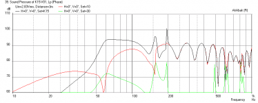
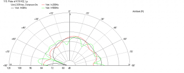
I added the ability to scale the length (height) and the width/depth independently. Doing this, I tried putting a Fostex FF225WK in a K15 box scaled in all dimensions to a smaller cabinet with the scaling factor of 8/15=0.53. This will give a 447 mm high cabinet, 242 mm deep, and 302 mm wide. In other words, a proportionally sized cabinet compared to the original K15. The frequency response is just awful - it ruined the speaker as you can see. So obviously, one cannot just shrink the cabinet all around for a smaller driver and expect it to sound good. However, I shrunk it in just the width and depth, but kept the height the same ("Skinny" version). This produced a nice flat bass shelf down to 60 Hz as can be seen in second plot. So it seems that if one wants to shrink the cabinet size, more path folding will need to be done to preserve the internal TL length - and this is apparent in the multitude of smaller cabinet variants of the Karlson that are available out there. Also shown are plots of the impedance and cone displacement for the "Skinny" version of the K15 with FF225WK. For grins, I added the VERTICAL polar SPL plot - notice the effect of the K-aperture ports on the low vs high frequencies. The bass is aimed downwards while the higher frequencies are lobed as you go from -90 deg to + 90 deg.
I added the ability to scale the length (height) and the width/depth independently. Doing this, I tried putting a Fostex FF225WK in a K15 box scaled in all dimensions to a smaller cabinet with the scaling factor of 8/15=0.53. This will give a 447 mm high cabinet, 242 mm deep, and 302 mm wide. In other words, a proportionally sized cabinet compared to the original K15. The frequency response is just awful - it ruined the speaker as you can see. So obviously, one cannot just shrink the cabinet all around for a smaller driver and expect it to sound good. However, I shrunk it in just the width and depth, but kept the height the same ("Skinny" version). This produced a nice flat bass shelf down to 60 Hz as can be seen in second plot. So it seems that if one wants to shrink the cabinet size, more path folding will need to be done to preserve the internal TL length - and this is apparent in the multitude of smaller cabinet variants of the Karlson that are available out there. Also shown are plots of the impedance and cone displacement for the "Skinny" version of the K15 with FF225WK. For grins, I added the VERTICAL polar SPL plot - notice the effect of the K-aperture ports on the low vs high frequencies. The bass is aimed downwards while the higher frequencies are lobed as you go from -90 deg to + 90 deg.
Attachments
Last edited:
I put together a model of the original 1955 John Karlson K15 (vented no slots) http://home.planet.nl/~ulfman/images/Plans/original.gif. I modeled the back chamber as a waveguide of varying cross sectional area prescribed by the plan (see drawings below). I modeled the front chamber as a waveguide of varying cross sectional area as well but with a series of 9 rectangular ports with CSA prescribed by a quadratic function that describes the K-slot. The two waveguides are connected by a common vent (the 165 mm x 85 mm wide port). The driver is an Eminence Kappa Pro 12A (http://www.eminence.com/pdf/Kappa_Pro_12A.pdf). Measurements are at 3 meters away with speaker set on stand so that driver centerline is 24 in above floor and wall is 5 ft back. Even at 3 meters away, the SPL is 90 dB at 1 watt.
The curve fit of the K-slot is quite accurate when I compared it to the prescribed numbers. The fit is given by Y=0.974X^2+0.00874X+0.0207. This is for X=0,1 and Y=0,1. Simply scale function for any slot based on max height and width at Y(X=1).
The frequency response shows a very strong bass response down to 60 Hz where it starts to decrease but has a decent SPL at 50 Hz. This is a very efficient speaker (the Eminence provides this). There are several dips and peaks as the frequency goes higher. I see a peculiar looking "W" shape from 150 to 200 Hz. Also shown are the impedance and cone displacement curves.
For anyone familiar with Karlson speaker measurements, does this look anything like it is supposed to? I may be completely missing the crucial points by modeling it as two waveguides connected by a vent with a leaky front waveguide. I think I may be missing something because this driver has an fs of 37 Hz and I am only getting 60 Hz peak.
By far, this was the most difficult and complex model I have done to date in AkAbak. It used about 30 nodes total.
This model has a universal scaling constant that will allow me to resize it en masse to shrink the cabinet and pop in a smaller driver. That immediately will impact the lower tuning freq as it depends on the path length.
Kool! That's some good work. I've never had a K15 myself, but from many of freddi's measurements plus what I measured from my K12 and SK8, I think you're fairly close. The "W" effect has been known to me ever since I started to measure Karlsons. For me, it marks the upper limit of the functional gain BW. This is where one should cross-over if wanting to use the Karlson as a bass enclosure only. There may be ways to minimize such artefacts for fullrange use. For simulating their bass performance as a BP6 enclosure, which is often accurate enough, the rear chamber tunes as a bass-reflex, but at a lower frequency than predicted by a BR simulation since th vent is mass-loaded by the air "trapped" in the front chamber. The front chamber probably has a few elements going on that determine its tuning, but for classic aspect-ration Karlsons, I think that the vetical dimension's QW resonance dominates. This frequency will usually be around 1.05 to 1.1 times the frequency dictated by the internal height. In any case, it can be set at Fb in the BP6 simulation as if it were a Helmholtz resonator, and Ql=3 usually approximates the de-Q'ing effect well enough.
Your findings about scaling-down are in line with the experimentation that has taken place through the years. Initially, Karlson was not recommending scaling down his K15, despite stating that it could be done if absolutely needed. Smaller models can become a bit problematic and I think it goes to prove that there is some QW action going on. He eventually came out with three different K12's and a re-configured, somewhat smaller K15, named X15, with an internal HF waveguide. This was initially a wooden "Rocket/Klam" driven by a cone tweeter and subsequently a metal (?) K-Tube with a University (I think) compression driver. There may have been pressure on him from the market since this was around the time Acoustic Suspension and Stereo became popluar and nobody wanted two hulking monsters in their living rooms anymore. Still, K12's can be pretty decent overall, but are probably more picky about the driver than K15. 8" drivers of medium motor strength can work fairly well in there. There was also a factory K8, with a few variations I believe. Freddi has some of these. The Super-K8, or SK8, actually of K10-size if going by scale-down based on K15, is about the smallest size practical with decent performance IMO, if keeping the classic form-factor. It was designed by a few members of the Karlson forum.
Smaller Karlson have been built with apparent good performance, but deviated in form-factor. Among these was the HAK6.5 (High-Aspect-Karlson) built for Fostex FF166En. Retaining some longer pathlength worked there. Even smaller units with folded TL back chambers have been said to be good. One was the Skip/Lee K-TL.
Getting low bass out of a Karlson can be somewhat hard since there is heavy cancellation below the rear chamber tuning. It usually has to be muscled-out with a very low Fs strong-motor driver (think Altec 416) and some EQ preferably. Karlsons seem to retain some cone-control below Fb still, so can probably take more EQ than a simple reflex.
I fudged a simulation of K12 as a tapped horn in HR a year or two back. I really cannot do a K-slot in there, so made a somewhat equivalent horn for the front chamber. The equivalency is not physical really, but more about matching the impedance and SPL curve. Driver is Philips AD9710, which I have used in K12. It was a very sensitive system, but not as much as shown below, subtract 3-5dB perhaps.
An externally hosted image should be here but it was not working when we last tested it.
An externally hosted image should be here but it was not working when we last tested it.
An externally hosted image should be here but it was not working when we last tested it.
An externally hosted image should be here but it was not working when we last tested it.
IG
Last edited:
- Home
- Loudspeakers
- Full Range
- Karlson