Hello jamikl,
I'm no longer in speaker building since ages and there fore can not give you any good advise on the matter.
The double karlsons I build long time ago were 140 cm high, I remember.
It was ONE cabinet with both the same speakers and a horn.
Remarks were very positive at the time, allthough they can no longer be considered HiFi nowadays.
But what the heck; if it sounds good for you then what do you care about the comments of others...
I allways say: " the first who start to give negative critics is politely shown the door"
Enjoy
hi - good motor strength and a rising response will help.
here are three plans - look at the large size downloads
Picasa Web Albums - greg muon - STUPID HIFI T...
Picasa Web Albums - greg muon - STUPID HIFI T...
Picasa Web Albums - greg muon - STUPID HIFI T...
here are three plans - look at the large size downloads
Picasa Web Albums - greg muon - STUPID HIFI T...
Picasa Web Albums - greg muon - STUPID HIFI T...
Picasa Web Albums - greg muon - STUPID HIFI T...
hi - good motor strength and a rising response will help.
here are three plans - look at the large size downloads
Picasa Web Albums - greg muon - STUPID HIFI T...
Picasa Web Albums - greg muon - STUPID HIFI T...
Picasa Web Albums - greg muon - STUPID HIFI T...
thanks a lot!! when the work will done i'll post some pic... bye

The SK6 looks really interesting. It is the first Karlson where I can understand what the flow path is doing. It appears to be a tapped horn with a variable terminus due to K slot. Thanks. ")
Can this work with other 6.5 or 6.0 in dtivers? What are TS params that one needs to keep simikar to FE166en?
Can this work with other 6.5 or 6.0 in dtivers? What are TS params that one needs to keep simikar to FE166en?
The SK6 looks really interesting. It is the first Karlson where I can understand what the flow path is doing. It appears to be a tapped horn with a variable terminus due to K slot. Thanks.
Can this work with other 6.5 or 6.0 in dtivers? What are TS params that one needs to keep simikar to FE166en?
With a somewhat weaker motor 6" (0.40<Qts<0.50) with not too large a Vas, I'd probably go for the SK6.5. For larger Vas, SK8 could work, but I see it as a bit large for a 6", afterall, going by classic scaling, it is actually a K10. HAK6.5 was reported to sound good with the FE166En and measured surprisingly well too!
In any case, for any of the above 3 enclosures, I'd try to keep the driver's mass-corner above 250Hz if possible. This is given by 2*Fs/Qts.
IG
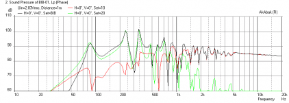
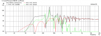
Effect of Karlson-like Holes on BIB
I am trying to get a feel for the effect of the Karlson aperture on existing speaker designs. I know some folks have tried adding a Karlson slot to the edges of their BIBs. I am trying to model the Karlson slot approximated as a series of holes of increasing diameter along the length of a speaker cabinet that has a horn or TL terminus. My fist model test case is a BIB using the small 3.5 in Vifa TC9FD. The first plot is the simulation of the plain BIB as prescribed by GM's BIB calculator (6 in wide x 8 in deep x 27 in tall with driver at 11.7 in from top) doesn't look too good with a pretty big dip at 125 Hz and two big sharp peaks at 250 and 350 Hz. The next simulation, I included 6 holes located as follows: 0.50 in dia at 23 in from the terminus, 0.6 in dia at 17 in from terminus, 0.75 in dia at 14 in from terminus, 1.0 in at 12 in from terminus, 2 in dia at 8 in from terminus, and 3.5 in dia at 5 in from terminus. These hole diameters are not following any prescribed "Karlson" exponential profile but hand selected to start small and located at convenient locations and slowly expanding at first and quickly expanding at the end. The point is you can infinitely "hand tune" these hole diameter and locations in real life with a hole saw and drill. The second plot shows a much improved flatter freq response, albeit you give up bass extension as expected. There is still a sharp peak at 350 Hz, which can probably be removed with more tweaking and adding holes to the speaker, and/or use of damping. The point is, the addition of swiss cheese holes can smooth the speaker response and knowing that bass extension is reduced, one just needs to start with a longer cabinet. Being able to model this before test drilling is a big plus. I am a believer in Karlson slots though - based on this exercise. I will try to model a K-slot speaker next.
I am trying to get a feel for the effect of the Karlson aperture on existing speaker designs. I know some folks have tried adding a Karlson slot to the edges of their BIBs. I am trying to model the Karlson slot approximated as a series of holes of increasing diameter along the length of a speaker cabinet that has a horn or TL terminus. My fist model test case is a BIB using the small 3.5 in Vifa TC9FD. The first plot is the simulation of the plain BIB as prescribed by GM's BIB calculator (6 in wide x 8 in deep x 27 in tall with driver at 11.7 in from top) doesn't look too good with a pretty big dip at 125 Hz and two big sharp peaks at 250 and 350 Hz. The next simulation, I included 6 holes located as follows: 0.50 in dia at 23 in from the terminus, 0.6 in dia at 17 in from terminus, 0.75 in dia at 14 in from terminus, 1.0 in at 12 in from terminus, 2 in dia at 8 in from terminus, and 3.5 in dia at 5 in from terminus. These hole diameters are not following any prescribed "Karlson" exponential profile but hand selected to start small and located at convenient locations and slowly expanding at first and quickly expanding at the end. The point is you can infinitely "hand tune" these hole diameter and locations in real life with a hole saw and drill. The second plot shows a much improved flatter freq response, albeit you give up bass extension as expected. There is still a sharp peak at 350 Hz, which can probably be removed with more tweaking and adding holes to the speaker, and/or use of damping. The point is, the addition of swiss cheese holes can smooth the speaker response and knowing that bass extension is reduced, one just needs to start with a longer cabinet. Being able to model this before test drilling is a big plus. I am a believer in Karlson slots though - based on this exercise. I will try to model a K-slot speaker next.
Attachments
Cool work once again!
The exact profile of a K-slot might not be very critical when it is used to gradually terminate a long pipe. This series of holes is probably just a good. It is another story in the Karlson bass enclosure where the slot also acts upon the front radiation of the driver. The slot probably needs to be of a certain dimension to do something helpful. I would not expect an 8" long by 4" wide slot to do much at the very end of a 80" pipe for example, at least nothing better than an equivalent sized rectangular slot. I'm guessing one probably wants the slot to cover some anti-node points of the higher pipe modes (5/4, 7/4, 9/4...) to de-Q these.
IG
Radio show from 1964 featuring a John Karlson interview:
John Karlson of Karlson loudspeaker fame speaks - 1964 radio - YouTube
(recorded in 1964 by Roger Russel)
John Karlson of Karlson loudspeaker fame speaks - 1964 radio - YouTube
(recorded in 1964 by Roger Russel)
Thanks IG. I will see if putting holes at the 5/4, 7/4, 9/4 etc anti-nodes has any effect on spoiling the Q of these cavity modes. The specific targeted drilling of holes to spoil the Q of undesirable modes may produce a more efficient speaker than just a a general Karlson aperture which is aimed at being smooth. But really, cavity modes are integer numbers and quantized, not continuous functions. So much may be lost in terms of acoustic power by making a long arc slot. I am surprised by how much SPL I can still retain at the lower freq by drilling holes.
Thanks IG. I will see if putting holes at the 5/4, 7/4, 9/4 etc anti-nodes has any effect on spoiling the Q of these cavity modes. The specific targeted drilling of holes to spoil the Q of undesirable modes may produce a more efficient speaker than just a a general Karlson aperture which is aimed at being smooth. But really, cavity modes are integer numbers and quantized, not continuous functions. So much may be lost in terms of acoustic power by making a long arc slot. I am surprised by how much SPL I can still retain at the lower freq by drilling holes.
I've been wanting to try a classic TL with antinode de-Q holes for a good while now, to see just how effective that is. In the foamcore thread, I presented a Nagaoka F-81 inspired enclosure with Fostex FF85WK. I made out its length to be a quarterwave of 1/3 of driver Fs, in order to use the 3/4 mode as the main pipe output and as a load at Fs. The 1/4 mode might still provide some damping way down there, though I don't know how useful it might be. The 5/4 and above modes were a problem above 150Hz or so, but simulation in HR shows me that placing the driver 1/5 down the line instead of Z=0 would retain much of the 3/4-mode advantages while almost fully suppressing the 5/4-mode peak. The higher modes can be killed efficiently with stuffing. De-Q holes might be fun to try here, as I might yet build it in wood.
IG
IG,
I remember your foam core (FC) Nagoaka F-81 with double-wall FC all around. That was a pretty cool speaker and hit an amazingly low freq for an FF85WK. What were the dimensions of the TL again? It was really long as I recall. Have you tried modeling it in AkAbak yet? I might try simulating this if you get me the dimensions and where all the bends are.
I remember your foam core (FC) Nagoaka F-81 with double-wall FC all around. That was a pretty cool speaker and hit an amazingly low freq for an FF85WK. What were the dimensions of the TL again? It was really long as I recall. Have you tried modeling it in AkAbak yet? I might try simulating this if you get me the dimensions and where all the bends are.
I had three segments and two bends. The three segments each were a bit larger in CSA than the previous, but that might not be necessary.
Basically, the length should be 224cm, for a quarterwave at 1/3 of driver Fs for FF85WK. Either a straight pipe (if easier) or three equal segments of equal CSA would be OK. I'm not too certain of how to optimize CSA here, HR is no real help. Maybe start with 3.5"x2.75" or so, that was my middle segment's CSA. Comparing driver offsets would be informative. Z=0 versus Z=44.8cm for example, for 1/5 placement. Placing the driver at 44.8cm (1/5) would be awkward in the form factor I had though. I was thinking of coming up with a box comprised of a tall section, maybe ~48", in order to have driver ~30" off the ground, and two smaller sections behind.
I wonder what was the rationale behind the original F-81. It was designed for the old FE83/FE83E, which had Fs~140Hz IIRC. It was a ~12ft pipe. |8^o
IG
IG,
I was searching for dims on the original F-81 and just saw your posts on fullrangedriver forum... how do you have time to keep up with two forums? It seems the F-81 is a gradually expanding TL, should I model it per original or as a straight TL as you suggest above? How did you build the FC ? Straight or expanding?
I was searching for dims on the original F-81 and just saw your posts on fullrangedriver forum... how do you have time to keep up with two forums?
It seems the F-81 is a gradually expanding TL, should I model it per original or as a straight TL as you suggest above? How did you build the FC ? Straight or expanding?IG,
I was searching for dims on the original F-81 and just saw your posts on fullrangedriver forum... how do you have time to keep up with two forums?
I also hang out on AK, AA and used to be on the Karlson forum.
Yeah, F-81 slowly expands, though each segment is linear. I built my FC box the same, but since I expected a slow expansion to tune higher than I wanted, since I had my exact 224cm length, I slightly mass-loaded the terminus (~0.5*SL) to bring the tuning back down to ¼-wave at 1/3*Fs. A straight pipe would be easier to simulate and a simpler build as well, might as well go this way right off the bat and make changes later if it could be deemed to improve things.
IG
OK, I will model a 3-fold (qnty 3 x 180 deg turns) 2.24 meter long straight TL with CSA of 3.5 in x 2.5 in. Driver will be at z=0 per Nagoaka F-81 and terminus will exit pointing up and in the back. I recall yours actually exited down and to the side? Note that a 30 in x 20 in FC panel designed to have 3 folds (4x30 in = 3.04 m pathlength). Where do you want to start putting de-Q'ing holes to start off with?
OK, I will model a 3-fold (qnty 3 x 180 deg turns) 2.24 meter long straight TL with CSA of 3.5 in x 2.5 in. Driver will be at z=0 per Nagoaka F-81 and terminus will exit pointing up and in the back. I recall yours actually exited down and to the side? Note that a 30 in x 20 in FC panel designed to have 3 folds (4x30 in = 3.04 m pathlength). Where do you want to start putting de-Q'ing holes to start off with?
Thanks for undertaking this again. If it's not too much of a hassle, can you compare Z=0 to Z=1/5 down the line? I would try to snipe the 5/4 mode this way, since the diaphragm is small and the line quite long, and try de-Q holes for killing 7/4 and 9/4 modes. Here are the Z offsets for de-Q holes for each mode:
7/4-mode:
32cm
96cm
160cm
9/4-mode:
24.89cm
74.67cm
124.45cm
174.23cm
IG
- Home
- Loudspeakers
- Full Range
- Karlson