Good luck, mate. There'll be music from coast to coast down under by New Years I reckon. 
If I should recommend something it would be to make sure the baffles that holds the speakers are the ones that are 300mm wide. Otherwise it can be a little flimsy when the woofer cut-out is made.
OH, and yeah, I just discovered this thread. Probably should've asked your questions in the Boominator thread instead.
Last edited:
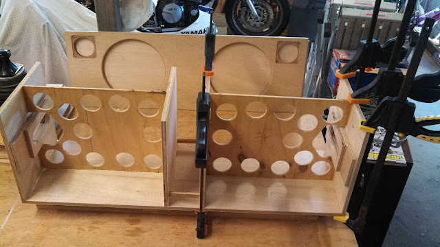
A whole day of cutting, drilling and routing has gotten me a little closer!
Air vents/handles to drill/route, and recessed tweeter holes to saw/route.
Then I think the box's will be ready to assemble/glue.
Air vents/handles to drill/route, and recessed tweeter holes to saw/route.
Then I think the box's will be ready to assemble/glue.
An externally hosted image should be here but it was not working when we last tested it.
An externally hosted image should be here but it was not working when we last tested it.
An externally hosted image should be here but it was not working when we last tested it.
An externally hosted image should be here but it was not working when we last tested it.
Hey!! Nice build!!
Congratulations
As of the series piezo resistor, you needn't calculate it as if setting a "crossover point" , that's taken care of, like it or not, by the physical vibration properties of the disk itself.
That it's "seen" as a cap is , let's say, a "side effect".
You simply add a series resistor so impedance does not fall too much at high frequencies, plus most amps do not like capacitive loads.
Any empirical value you choose is fine.
I use 10r to 47r , depending on what's on hand , and don't find any difference in sound.
Now 300 ohms I find a little too high, and it will pad the output in general, or makes it somewhat duller.
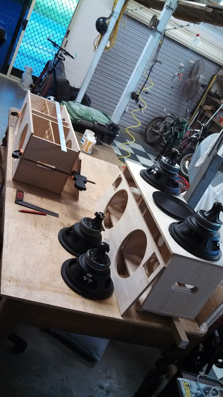
All holed drilled, routed and jigsawed. Test run fitting.
A jig I made to do the rebate routing for the tweeters
Gluing the internal bracing (picture would not upload)
Screwed woofers and tweeters in, wired in one side to L & R , soldered in the resistors for a quick sound test... going to sound AWESOME!
Getting closer!
An externally hosted image should be here but it was not working when we last tested it.
A jig I made to do the rebate routing for the tweeters
An externally hosted image should be here but it was not working when we last tested it.
Gluing the internal bracing (picture would not upload)
Screwed woofers and tweeters in, wired in one side to L & R , soldered in the resistors for a quick sound test... going to sound AWESOME!
An externally hosted image should be here but it was not working when we last tested it.
Getting closer!
Tested with all speakers hooked up, but only held together with clamps, and it sounds like it has the possibility to sound good once it's fully sealed.
Wire I used was too heavy, as couldn't get all 4 wires together to go into the speaker post clamp. so I'll get some lighter wire when I do the final put together.
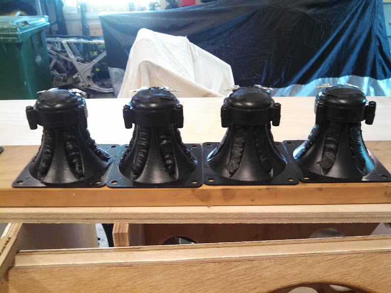
I need to get some 'rope caulk' or putty to dampen the tweeters and some epoxy for the woofers front and rear mounting.
Also the Batteries I have are too big, so I am going to grab 2 x 12v 7ah from the local battery shop and stack them.
The gluing has begun.
Wire I used was too heavy, as couldn't get all 4 wires together to go into the speaker post clamp. so I'll get some lighter wire when I do the final put together.
I need to get some 'rope caulk' or putty to dampen the tweeters and some epoxy for the woofers front and rear mounting.
Also the Batteries I have are too big, so I am going to grab 2 x 12v 7ah from the local battery shop and stack them.
The gluing has begun.
Second boominator being created, much like the first one.
Once they are both ready for internal treatment (water proofing).
Then I can proceed with Modding the piezo's and mounting the grill's & woofers to the baffles.
Still working out the power side of things and weither I'll mount the charger in the box ( just need a power plug then to charge it).
Cheers, S.
Slow progress.
Spent a fair amount of time working out what I was going to do with the battery/amp mounting, and ended up with a solution.
Did not want to fully seal the whole thing, so i am going to make the top removable, will seal with a thin rubber lining around the eadges and brackets and bolts to hold the top on firmly should make it air tight enough that I won't compromise the DB levels by not full sealing it, but make it accessable to change batteries and access to speakers etc.
I also wanted all sides to look seamless.
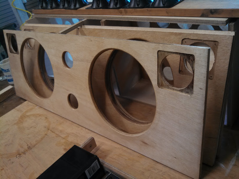
Cut and route some air vent holes in the baffles.
Painted the inside wall of the baffles in while undercoat.
Rubbed in a clear polyurethane coating on the outside of the baffles.
apply some gap filler material treatment to the tweeters.
Spent a fair amount of time working out what I was going to do with the battery/amp mounting, and ended up with a solution.
Did not want to fully seal the whole thing, so i am going to make the top removable, will seal with a thin rubber lining around the eadges and brackets and bolts to hold the top on firmly should make it air tight enough that I won't compromise the DB levels by not full sealing it, but make it accessable to change batteries and access to speakers etc.
I also wanted all sides to look seamless.
Cut and route some air vent holes in the baffles.
Painted the inside wall of the baffles in while undercoat.
Rubbed in a clear polyurethane coating on the outside of the baffles.
apply some gap filler material treatment to the tweeters.
An externally hosted image should be here but it was not working when we last tested it.
Batteries will be in Parallel to get a full day at full power
Stole this off another post about getting the charge circuit right as I cannot justify the solar panels.
Original thread http://www.diyaudio.com/forums/power-supplies/192045-charge-12v-sla-while-using-amplifier.html
I mainly wanted the info on the circuit in this simplified version:

So from this I can assume that I can basically plug in any SLA battery charger and it should be able to charge the battery and supply amps to the stereo if left on.
Assuming the the battery + charger can supply enough current to: run the amp & charge the batteries...
I have a selection of 3 chargers from link 1 - 1amp, link 2 - 1.8amp and link 3 - 4amps or something else?
What I want to achieve is to be able to just use a regular IEC computer socket mounted on the Boominator, then I can basically plug the Boominator into the wall to charge the batteries (Charger is permanently mounted inside the Boominator).

1. 12V 1 Amp Sealed Lead Acid Battery Charger - Jaycar Electronics
2. 1.8 Amp 6/12V Sealed Lead Acid Battery Charger - Jaycar Electronics
3. JAYLEC BC9000 SMART BATTERY CHARGER 12V CAR MOTORBIKE CARAVAN AGM DEEP CYCLE SLA | eBay
Stole this off another post about getting the charge circuit right as I cannot justify the solar panels.
Original thread http://www.diyaudio.com/forums/power-supplies/192045-charge-12v-sla-while-using-amplifier.html
I mainly wanted the info on the circuit in this simplified version:
So from this I can assume that I can basically plug in any SLA battery charger and it should be able to charge the battery and supply amps to the stereo if left on.
Assuming the the battery + charger can supply enough current to: run the amp & charge the batteries...
I have a selection of 3 chargers from link 1 - 1amp, link 2 - 1.8amp and link 3 - 4amps or something else?
What I want to achieve is to be able to just use a regular IEC computer socket mounted on the Boominator, then I can basically plug the Boominator into the wall to charge the batteries (Charger is permanently mounted inside the Boominator).
1. 12V 1 Amp Sealed Lead Acid Battery Charger - Jaycar Electronics
2. 1.8 Amp 6/12V Sealed Lead Acid Battery Charger - Jaycar Electronics
3. JAYLEC BC9000 SMART BATTERY CHARGER 12V CAR MOTORBIKE CARAVAN AGM DEEP CYCLE SLA | eBay
Yes, handles are doubling as reflex ports. And was calculated for surface area and depth by saturnus in the big boominator thread.
My metal cement I bought will not work, so I will have to resort to alternate glue is liquid nails etc, as the metal and agent go off too fast for me to mount the grills. (Too humid).
My metal cement I bought will not work, so I will have to resort to alternate glue is liquid nails etc, as the metal and agent go off too fast for me to mount the grills. (Too humid).
Had an hr or so spare today so the grills are being glued in. I decided to also glue some speaker cloth over the heat holes, only that I know those damn paper wasps will try to build their mud nest in any place they can find...
An externally hosted image should be here but it was not working when we last tested it.
Some more progresses.
One set of woofers glued in.
Wanted to have the top removable, so some customs bolt brackets were built from various bits from a visit to Bunnings
Shelf bracket, 25mm m6 bolt and nut, some screws. It will be sealed with a gasket of cork and rubber when I finally seal it up, so should be air tight enough, but I still may loose 1/2 or 1 db, but I would rather that so I can still access the amp, batteries etc.
The brass hex nuts don't detract from the overall feel, and they are quite flat.
Sent from my XT925 using Tapatalk 2
One set of woofers glued in.
Wanted to have the top removable, so some customs bolt brackets were built from various bits from a visit to Bunnings
Shelf bracket, 25mm m6 bolt and nut, some screws. It will be sealed with a gasket of cork and rubber when I finally seal it up, so should be air tight enough, but I still may loose 1/2 or 1 db, but I would rather that so I can still access the amp, batteries etc.
The brass hex nuts don't detract from the overall feel, and they are quite flat.
An externally hosted image should be here but it was not working when we last tested it.
An externally hosted image should be here but it was not working when we last tested it.
Sent from my XT925 using Tapatalk 2
Looks awesome! I'm about to build my first boominator. Very excited! :-D - I'm wondering were you're got those woofer speaker grills, they look more sweet than the "usual". Unfortunately, i'm from Denmark, so I can probably not get them the same place as you, so do they have a name or anything else? - Also, do you know how well LED diodes lights through the grill?Woot, found some reasonable priced woofer grills. Ordered!
Still need:
Wood
Resistors for piezo's
Batteries
Circle jig (going to make a diy jig for my router)
Some alluminium L shape for edging
Some glue/cement to join the hp10w magnets back to back.
---
I am here: http://maps.google.com/maps?ll=-21.171309,149.127210
- Status
- This old topic is closed. If you want to reopen this topic, contact a moderator using the "Report Post" button.
- Home
- Loudspeakers
- Full Range
- Alternate Full range 10" drivers