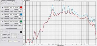
Some investigations concerning selective stuffing/damping ...
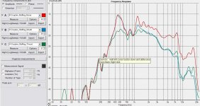
Curves taken at
- about 1m distance
- about 30 degrees above the tube's axis (at the slot side).
(that means falling slope even in "unstuffed" setting)
"Stuffed throat" means about 10cm in length of the tube from
driver to beginning of the slot, not "pressed hard" but not
"loose" either.
In my view, stuffing such a device is essential to get balanced
output, like in any quarterwave design.
Of course highs are muffled by doing so, maybe the
"covered slot" setting can be refined if highs are essential.
Here the "stuffed throat" condition is the only one giving
a quite acceptable midrange from say 300Hz to 3Khz.
A lining of the tube has not been tested yet.
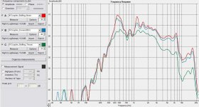
Attachments
Last edited:
Here's a French test of 3 types of tubes as waveguides, straight-cut, elliptical and K-slotted. I can't help but think the K-Tube got the short end of the stick in more than one way though.  The cut itself is barely more than a shallow half-ellipse and the whole thing is quite short.
Fichier d?origine: Acousticaltube.pdf
IG
The cut itself is barely more than a shallow half-ellipse and the whole thing is quite short.Fichier d?origine: Acousticaltube.pdf
IG
Thank you for posting, i have already seen this experiment
on the web.
I think if one was to compare the shape of cutouts/mouths
one should align for same lambda/4 lowest resonance.
That means the elliptical would have to be significantly longer
then the "straight" cut and the K-slot even (much) longer.
So the base quarterwave resonance would be a useful kind
of "norming" for comparison of impedances etc.
But here the elliptical and K-slot types are even much
shorter than the straight cut, thus comparison does not
reveal anything surprising IMO.
Last edited:
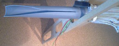
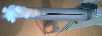
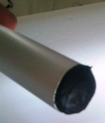
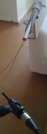
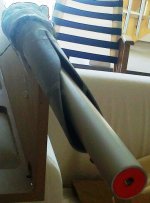
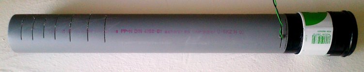
Using a phase plug like shown on the pics.
The phase plug reduces the cross sectional
area of the K-tube's throat from about
16 cm^2 to 7 cm^2
Inner tube outer diameter approx. 30mm
Outer tube inner diameter approx. 45mm
The inner tube is sand filled and closed
at both ends
A piece of kneading mass forms the compression
chamber at the inside end of the inner tube.
Compression ratio for given driver is near 2
The "phase plug" inner end has been brought
as close as possible to the diaphragm, without
the diaphragm touching the plug at low frequency
movement (should be about 1mm distance).
Comments after coffee break ...
Attachments
Last edited:
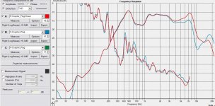
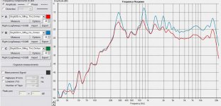
Variation of the pressure chamber volume ...
The phase plug including pressure chamber has little
effect at low frequencies, despite distorsion being
lower without compression chamber near the lower
cutoff of the tube.
For the top end it is important to have the chamber
volume as small as possible.
Nevertheless in the current device there seems no
benefit from the phase plug.
Attachments
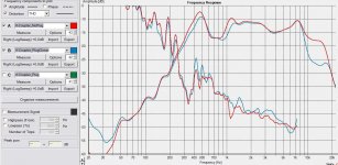
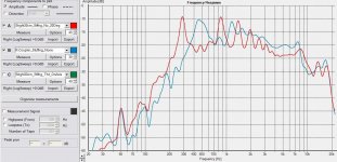
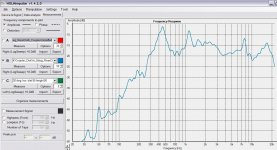
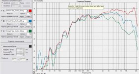
Now a 30cm long straight cut tube ...
A) Stuffed throat (approx 10cm) vs. unstuffed, on axis
B) Stuffed throat (approx 10cm) vs. unstuffed, approx. 20deg off axis
C) 30cm straight vs 38cm K-Slot both unstuffed, Caution: Conditions and
levels not identical, just for qualitative comparison
__________________________
What are the effects of the K-Slot compared to straight cut ?
- effective acoustical length shrinks > lowest quartewave resonance rises in frequency
- higher order resonances have lower Q, dampening effect similar to stuffing
- little/no effect on overall efficiency
- little/no effect on radiation/dispersion of high frequencies with wavelengths
comparable to diameter of tube
Some personal conclusions:
1) K-slotting may be used to complement damping by porous materials due to resonances of low
to mid order numbers.
2) It is questionable, whether noteably shrinking the effective acoustical length of the tube
by "K-slotting" is worth that potential benefit, since an effectively shorter tube tends to have
worse modal overlap.
Attachments
Last edited:
3) Length and (strategic, local) damping of the quarterwave tube
are the main factors for the usable low frequency extension.
Moderate K-slotting (not too long slot) may allow for reduction of
porous material to be used and from this point of view increase
efficiency at HF a little, if the tube was stuffed already.
But there is no significant effect on high frequency radiation as such.
First time I see a phase plug on a K-Tube. That's some pretty involved testing there!
Subjectively, the 1" format K-Tube really does seem to do a good job at dispersing HF. Listening to a mono Karlson topped with a K-Tube makes for a wide sound despite mono.
I'll see if I have data anywhere on this or maybe I can measure some.
Keep up the work, there's not many folks playing with these and they can sound good.
IG
Thanks IG,
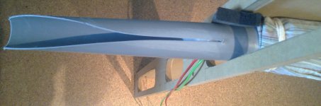
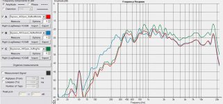
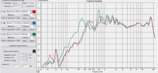
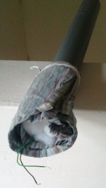
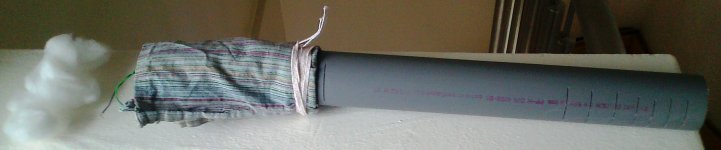
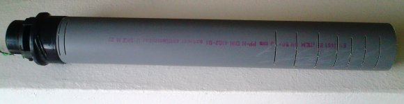
now for some "alternative" design for comparison ...
From left to right
A) B) C) "Making Of" a 35cm in length quarterwave tube with "resistive bypasses",
............only estimatedly positioned at potential area of max. pressure
............for the lowest resonance and the "near mouth pressure maxima" for
............the higher order modes.
............(Bypasses at throat and in the last third near the mouth)
D) K-Coupler style 37cm in length
E) Measurements of "bypassed tube" without stuffing
D) some measurements including stuffing (approx. 8cm in length between the bypass areas)
F) K-Coupler measurement from a setting before, not directly comparable due to signal level and
positioning, but same smoothing (1/6 octave) like E) and D)
All measurements "on axis approx. in line with the tube / K-coupler respectively
____________________
Of course the bypasses could be optimized in position and also a "mouth slot" in line
with the tube would be possible - but this kind of PP tube better keeps circular cross
section if slotted this way ...
Even the "resistive bypass slots" cause effective acoustical shrinking of the tube
(lowest resonance rises in frequency) as a (in my case unwanted) side effect, but
that is no surprise.
The last measurement did not hit the "most beautiful radiation angle" of the K-Coupler
style tube ... nevertheless the "bypassed" counterparts are able to keep up in terms
of bandwidth and ripple/smoothness.
In fact from these measurements the K-slot type does not look very well.
More precise comparison and optimizations would have to be done, but at this point
damping and "resistive slotting" seem more attractive to me to get a usable midrange.
Attachments
-
 Measure_K-Coupler_Length37cm_StuffingNo_00Deg.JPG189.5 KB · Views: 72
 -
 Measure_Bypasses_Stuffing.JPG183.2 KB · Views: 88
 -
 Measure_Bypasses_OpenVsClose.JPG183.5 KB · Views: 227
 -
 K-Coupler_Length37cm_StuffingNo.jpg563.9 KB · Views: 246
 -
 Tube_Length35cm_ResistiveBypasses_03.jpg534.6 KB · Views: 245
 -
 Tube_Length35cm_ResistiveBypasses_02.jpg398.8 KB · Views: 252
 -
 Tube_Length35cm_ResistiveBypasses_01.jpg392.8 KB · Views: 253
Last edited:
...
2) It is questionable, whether noteably shrinking the effective acoustical length of the tube
by "K-slotting" is worth that potential benefit, since an effectively shorter tube tends to have
worse modal overlap.
...
Which of course argues for the strategy in the
Faerber design, i was talking so impolitely about before ...
If used for high frequencies only, long tube with relatively
short K-Slot slot seems a valid approach.
Unfortunately i am searching for usable midrange too.
@IG : Small diameter compared to wavelength surely is
preferable, as you stated before, to have acceptable dispersion
in highs.
For larger membranes needed for midrange maybe use a
compression chamber of moderate ratio, to adapt a
sufficiently small diameter tube.
Last edited:
A proposal for discussion:
|<-----dipole path length----->|
D-----------------------------D
D..................::::..................D
D...=======..::::..=======...D
D..................::::..................D
D-----------------------------D
D One driver at each side of the tube wired in antiphase
-- tube wall
.. porous damping material inside tube
:: increased stuffing ( e.g. foam plug)
== resistive slots
______________________________________
Goal would be having a wide range (mid- to high frequency)
dipole radiator without baffle in shape of a low profile rod.
For efficient LF radiation sufficient dipole path
length is needed.
But with larger separation of sound sources
also side lobes will occur at lower frequencies.
Resistive slots may be used to
- suppress side lobes
- damp the tube's resonances occuring now at N x lambda/2 (N odd)
Increased stuffing in the middle of the tube to
- (also) damp the tube's resonances occuring at N x lambda/2 = tube_length (N odd),
where velocity maxima occur in the middle of the tube
________________________________________
Would it be possible for the arrangement to be aligned in a way that
- LF operaton is like a dipole with moderate loss due to leakage
(aligned/compensated by dipole path length) ?
and at the same time
- towards higher frequencies a "smooth morphing" into two cardioids
(in form of resistance boxes) each radiating in opposite direction
takes place, having only moderate side lobes ?
Last edited:
Do I get it right, that your proposed arrangement would have the drivers working push-pull? Sharing the same cavity, when the drivers are "out of phase" for frequencies with too short a wavelenght, it might start to act weird, so that's where I'm guessing that the damping should be arranged in a way to prevent any ill effect.
IG
IG
Do I get it right, that your proposed arrangement would have the drivers working push-pull?
...
Yes, i thought about doing so. Resonances should not be any different,
than using half of the tube (single side open) and only one driver.
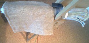
Anyhow, i used the
- 35cm slotted one from above,
- single (rear) side open,
- completely stuffed (from driver to open rear end)
to mount the driver in conventional arrangement.
So some "tube modding" was used to make a usual quarter
wave tube virtually free from resonant conditions in midrange
and mount a driver to radiate conventionally ...
I guess all who followed this comic strip might agree,
that smoothness in midrange is not approached by any of
the "tube radiators" tested before.
Even in this state, the lower rolloff is quite acceptable and
should integrate well using a simple filter slope.
Attachments
Last edited:
Geometrical length including the tin adaptor is about 40cm.
With that rather tight stuffing used the tube seems to be
effective down to about 250Hz, which would propose an
effective length of 0.3m assuming c=300m/s
(which might be approximatly right inside the stuffed tube)
or
0.34m if using c=340m/s (when using sound in air for
estimation of effective length)
To have the tube effective down to Fs of the driver the
tube could even be extended to 0.53m effective length,
about 0.34 x 1.6.
But depending on how to use it, that length may be somewhat
impractical, because the new tube would have to be about
0.64m long geometrical, protruding most woofer cabinets in depth,
when keeping it straight.
Last edited:
- Status
- This old topic is closed. If you want to reopen this topic, contact a moderator using the "Report Post" button.
- Home
- Loudspeakers
- Full Range
- Widerange dipole with Karlson Couplers ?