finally realised why those CSD plots are seemed completely useless to me!
there was horrible resonances and still too much room interaction going on. once i'd tightened up my testing conditions it actually worked like i thought it should have.
i've created a horrible shriek at 4khz but i think made the rest of the ride smoother?
![IMGDEAD]](/community/proxy.php?image=http%3A%2F%2F%5BIMGDEAD%5Dhttp%3A%2F%2Fimg33.imageshack.us%2Fimg33%2F9968%2Fmodwaterfall.gif%5B%2FIMGDEAD%5D&hash=ce66a79ec8ad6d030ac521125ff4d1d5)
there was horrible resonances and still too much room interaction going on. once i'd tightened up my testing conditions it actually worked like i thought it should have.
i've created a horrible shriek at 4khz but i think made the rest of the ride smoother?
Last edited:
applied some EQ to the signal. i can appreciate the EnABL process a lot more now the FR
is less appalling. somewhat counter-productive having to EQ the devil out of a driver in order to appreciate something i feel.
is less appalling. somewhat counter-productive having to EQ the devil out of a driver in order to appreciate something i feel.
An externally hosted image should be here but it was not working when we last tested it.
i've damn near deafened myself but i've finally tracked down the source of the shriek at 4khz. i fashioned myself a small ear horn and slowly moved the it over the surface of the cones and the surround. located it to the gap that remained between the the edge of the whizzer and the phase plug.
i've now lightly attached some cotton wool to the Zag glue at the base of the whizzer and the shriek has been reducing and it has also seemed to reduce some of the other wobbles. i also did the same over the stock driver, it had far more hotspots in the whizzer but shared a hotspot at the base joint between the dustcap and the whizzer itself.
i've made a hell of a mess and now have a very furry speaker but its taken another step towards civilised sound.
An externally hosted image should be here but it was not working when we last tested it.
An externally hosted image should be here but it was not working when we last tested it.
IIRC there is quite a gap between the VC former & your phase plugs. Something on the order of 0.5-1mm gap is what you want to aim for on your next set.
dave
yeah, i need to improve my wood turning skills. i had intended for it to be fairly flush but taking a little bit off here and there adds up

and there's the end of these drivers and quite frankly any chance of me attempting to EnABL a good pair. too much chance of error. i thought i followed EXACTLY the same methods and quantities as the first driver :S
probably still useful for something up to 500-1000hz, anything after that and they're ruined.
probably still useful for something up to 500-1000hz, anything after that and they're ruined.
An externally hosted image should be here but it was not working when we last tested it.
I do wonder why not more FR drivers come with a good phase plug fitted as standard?
They often seem to have a good effect, and they cannot be too difficult to design and produce in a factory.
Getting ready to duck for cover, but....
It is my experience with Fostex, Pioneer and Radio Shack drivers that installing a phase plug has the effect of putting a hole in the response int 5-7kHz range. This has the effect of reducing sibilance in female voice. It makes for a more relaxed, less spitty sound. My guess is that manufacturers would prefer a flat FR though this band and let the user "color" the sound.
Bob
that is exactly what has happened here Bob, so you're entirely correct as far as this model is concerned. its a pain that required some EQ but it sounded far better with them, than without.
although they're essentially dead now as they're night and day in terms of sound, i am still planning on playing with the working unit with phase plug designs as i think that dip can be lessened or avoided with the correct shape.
Last edited:
managed to drag these back from the grave slightly. they kinda match now, actually a bit better than the stock drivers did, until you get up to 8-9khz region then they separate again.
An externally hosted image should be here but it was not working when we last tested it.
finally realised why those CSD plots are seemed completely useless to me!
there was horrible resonances and still too much room interaction going on. once i'd tightened up my testing conditions it actually worked like i thought it should have.
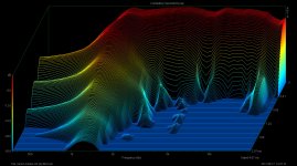
I hate break this to you, but the CSDs you've presented are completely meaningless for testing driver resonances due to completely unsuitable scales chosen. You have a vertical axis amplitude range of 70dB, you should be using around a 25-30dB vertical range.
The second problem is your time scale, you are using a whopping 300ms - driver resonances, even bad ones, decay in the first few ms, what you are seeing is the decay pattern of your room!
Your time scale should be a minimum of about 2ms and maximum of about 4ms depending on how quickly the driver resonances decay. (I prefer 2ms for best accuracy but some drivers have bad resonances that take longer than 2ms to decay)
Finally, if you are seeing a decay (your room decay in fact) which lasts for hundreds of milliseconds, it means that you are not properly gating/windowing out the room reflections - this is absolutely critical as a CSD will become invalid if even one significant room reflection is allowed into the impulse window time period.
Depending on your measurement setup, (distance from speaker/microphone to boundaries etc) the maximum valid window time may be as short as 3ms and almost certainly no longer than about 6ms. If you have a window time much longer than this then the results will be invalid even if the amplitude and time scales were suitably set.
It's also a good idea to set the start marker a small but known distance ahead of the impulse so that you have a small section of level response in the graph before decay starts - I normally use 0.4ms for this. Otherwise the decay can appear to start before the zero time on the graph giving an inaccurate result.
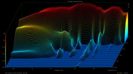
I've attached a couple of images of CSD's done right as an example - two different tweeters, a 30dB amplitude scale, 2ms time scale, and reflections correctly windowed out, (in this particular measurement set-up a gate time of 4.67ms) and as you can see its very easy to identify differences in the resonances of the two drivers with no contribution from room effects...
Attachments
Last edited:
- Status
- This old topic is closed. If you want to reopen this topic, contact a moderator using the "Report Post" button.
- Home
- Loudspeakers
- Full Range
- phase-plugging