While examining the measurements of the Thiel PCS at Stereophile, I noticed that it's a 'fake' coaxial.
Here's what I mean by this:
To make a 'real' coaxial, you put a tweeter inside the voice coil of a midrange driver. Companies like Seas, Kef, and Tad all sell speakers like this.
It's a challenge to make the driver small enough - and I've long been impressed that Thiel's "coaxial" is so small.
But upon reading further, it's NOT a real coaxial. What they call a 'tweeter' is merely the dust cap on the midrange. The 'trick' is that the 'tweeter' is isolated from the midrange by a damping ring.
This is quite clever - and the measurements are as good as any I've seen:
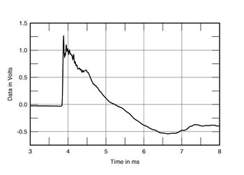
This is the step response with their "coaxial"
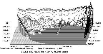
This is the waterfall plot of a Thiel CS3.6, which uses a Vifa midrange and tweeter that are seperated by 4.5"
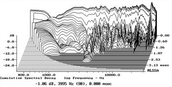
This is the waterfall of their fake coax in the PCS loudspeaker. That's a beautiful plot!
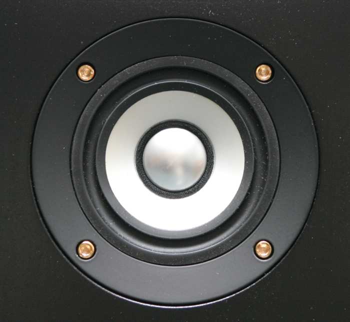
Here's the driver in question. Reminds me of a Fountek or an Alpair, but that damping ring is clever.
From their website:
"The most unusual technical feature of the PCS is its use of a
compound driver where the tweeter dome and the midrange cone
are both driven by a single voice coil. The design is implemented
with a mechanical crossover – a “coupling” suspension between
the coil and the midrange cone. The stiffness of the coupling
suspension is sufficient so that at low frequencies the voice coil
moves both the tweeter dome and the mid cone in unison.
However, at high frequencies the coupling suspension’s
compliance is sufficient to “decouple” the mass of the mid
diaphragm from the movement of the coil and dome.
The advantages of this unique driver are that perfectly time-
coherent performance is achieved without the cost and
complexity of two magnet structures or an electrical crossover
network for the mid-to-tweeter transition. By optimizing the
compliance and damping of the coupling suspension and the
ratios of area and mass of the two diaphragms, the driver
exhibits extremely uniform response from 100 Hz to 20 KHz."
[/font]
Here's what I mean by this:
To make a 'real' coaxial, you put a tweeter inside the voice coil of a midrange driver. Companies like Seas, Kef, and Tad all sell speakers like this.
It's a challenge to make the driver small enough - and I've long been impressed that Thiel's "coaxial" is so small.
But upon reading further, it's NOT a real coaxial. What they call a 'tweeter' is merely the dust cap on the midrange. The 'trick' is that the 'tweeter' is isolated from the midrange by a damping ring.
This is quite clever - and the measurements are as good as any I've seen:
This is the step response with their "coaxial"
An externally hosted image should be here but it was not working when we last tested it.
This is the waterfall plot of a Thiel CS3.6, which uses a Vifa midrange and tweeter that are seperated by 4.5"
This is the waterfall of their fake coax in the PCS loudspeaker. That's a beautiful plot!
An externally hosted image should be here but it was not working when we last tested it.
Here's the driver in question. Reminds me of a Fountek or an Alpair, but that damping ring is clever.
From their website:
"The most unusual technical feature of the PCS is its use of a
compound driver where the tweeter dome and the midrange cone
are both driven by a single voice coil. The design is implemented
with a mechanical crossover – a “coupling” suspension between
the coil and the midrange cone. The stiffness of the coupling
suspension is sufficient so that at low frequencies the voice coil
moves both the tweeter dome and the mid cone in unison.
However, at high frequencies the coupling suspension’s
compliance is sufficient to “decouple” the mass of the mid
diaphragm from the movement of the coil and dome.
The advantages of this unique driver are that perfectly time-
coherent performance is achieved without the cost and
complexity of two magnet structures or an electrical crossover
network for the mid-to-tweeter transition. By optimizing the
compliance and damping of the coupling suspension and the
ratios of area and mass of the two diaphragms, the driver
exhibits extremely uniform response from 100 Hz to 20 KHz."
[/font]
This implementation of what is usually called a decoupled cone, is prior art,as there are many examples of the technique to be found in earlier speakers.I can recall an early version of a Richard Allen CG8T that seperated the main cone from the whizzer cone (which was directly attached to the voice coil assy.)via one corrugation of the concentric centering disc.The only problem with this method is that careful attention to detail is required to maintain consistency and avoid a peak and dip situation at the mechanical xover freq.There is another related system used by Barker Duode and the early Hartley Turner speakers where the decoupling takes place in the voice coil by way of a latex sleeve between the winding and the aluminium former which drives the H.F. dome.Then there were the Altec bi-cones and others.J.M. Kates covered this subject in the AES journal ,Jan/Feb 1977.
Hi there PB & VN: I have an Advent 6.5i ICT louadspeaker, made in USA, to a British liscence for mobile use. Measures 6.1" frame diameter with a smallish 4.5" Sd measurement. The tweeter unit is fitted into the an anular space between a plastic wizzer device (attached to the main cone) and the pole. As explained in the liturature, the tweeter was mechanically crossed-over (?). WT-3 measurements: Re=3.09, Fs=74.7 Qts=0.69, Qes=0.84, Le=0.45, MMs=2.94, Vas=0.81, Spl=92.4.... regards, Michael
You have to be very careful in comparing waterfall plots. The first thing I notice about these is that the y axis sensitivity is completely different. If you chop the lower portion (16 db or so) of the vifa one it will look something like the PCs one!
Kevin
I'm far from an authority on loudspeaker phase, but I *think* this is what we're seeing in the graph:
- The vertical height of the two graphs is actually the same; although one starts at zero dB and one starts at 18dB, the number of dB on the vertical axis is identical.
- According to John K's site, the group delay of a driver will grow as we get closer and closer to the free air resonance:
An externally hosted image should be here but it was not working when we last tested it.
An externally hosted image should be here but it was not working when we last tested it.
In the graphs above, the group delay of the filter begins to increase about four octaves above the -3dB point of the filter. (The group delay is the light blue line, the phase is the red line.) - The combination of the driver's natural rolloff and the crossover filter will yield a lowpass which is steeper than a first order. When that combination exceeds a first order slope (as it usually will), we'll see additional group delay near the crossover point.
I *think* that is why we see a slower decay near 3000hz on the first graph. 3000hz is the crossover from tweeter to woofer on the first speaker, and the second two points noted by John K is inserting about one millisecond (13.5") of group delay at the low end of the tweeter's response.
The "faux-axial" waterfall plot doesn't suffer from this because there's no crossover filter and the transition from the center cone to the outer cone occurs at a frequency which is well above the resonance of the driver. (And it's the crossover filter and the driver's resonance which creates group delay in the first driver.)
Last edited:
As mentioned above, Altec produced some mechanical crossover drivers, the 419-8B and 420A (12" and 15"). Both had a mechanical compliance at about the 8" diameter point on the cone, crossing over about 1 KHz. They were therefore woofer/midrange drivers, rather than mid-bass/tweeter, though they had aluminium dome dust caps and were usable up to about 14 KHz. They called the design "Biflex".
Altec produced some mechanical crossover drivers, the 419-8B and 420A (12" and 15").
And let's not forget the 408, 412 and the 415.
")
Similar, the Tannoy ICT-
tannoy
That's clever. The metal tweeter dome appears to sit about where the copper shorting ring would go in a standard driver, and the eddy currents induced in it generate the force needed to move it.
And let's not forget the 408, 412 and the 415.
Oh, yeah. Memory is the second thing to go with age... I forget what the first one was.
- Status
- This old topic is closed. If you want to reopen this topic, contact a moderator using the "Report Post" button.
- Home
- Loudspeakers
- Full Range
- Has Anyone Built a Fake Coax?