Hi to all,
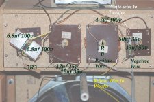
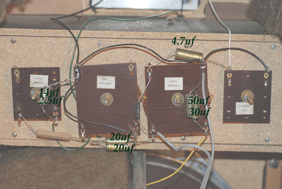
I am upgrading a pair of vintage Braun L-910s and the capacitors used for the crossover network are just dangling in the box and I need some advice on wiring issues. I have written the capacitor values over this image but I do not know how to draw a proper schematic.
Some of the film Caps I want to use are quite large. I am anticipating needing to change some of these wires and this is where I need some advice please. What kind of wire should I use here, does it matter what gauge it is or what length I need to use between each capacitor. I was thinking that just some or 16 or 18 guage Romex would work real well for bending and staying in place? I plan on using some really large Mundorf MKPs for the Woofer and I don't suspect I can maintain the configuration of the capacitor network as they currently appear. I am going to put in a shelf right underneath to support the large film caps but I will need to increase the wire length between the capacitors to do it. What do I need to consider if I were to do something like this or is a change in wire length like that a nominal change?
Also I would like to change the lamp chord to a passive biwire cable. I am currently using Audioquest Type 4 speaker cable and I would like to put it inside the box. For example, if I were to attach the 2 positive wires from the biwire cable to the current positive feed into the crossover network but then split it into 2, 5-way binding posts so I can passively biwire the speakers at the terminals is this o.k. to do or is it not that simple? Do I need to maintain the 2 terminal configuration or can I change it to 4.
Lastly, I have selected Russian K75-10s for the midrange drivers and tweeter with FT3 teflon bypass caps. I have a 4.7uf K75 and .1uf K4 bypass caps for the bass woofer as well. However, what would be some good resistors to replace the 2 resistors? I am assuming the black 1R0 is a 1W metal film (there is a 1 on it) and the Brown Ceramic resistor is 10W (its brown). I am not as adept at reading resistor values as capacitor values.
Important speaker information
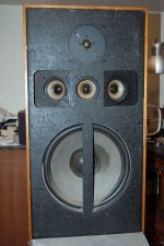
Loudspeakers: A 12-inch subwoofer, three 3-inch midrange systems
and a 1 inch tweeter system (spherical membrane).
Impedance of 8 ohms. Power 60 W
Transition frequencies of the built-in switch 300 and 3000 Hz
Frequency response 20 - 25000 Hz
Thank you for any and all input. This is my first speaker project.
Don't assume I know something

I am upgrading a pair of vintage Braun L-910s and the capacitors used for the crossover network are just dangling in the box and I need some advice on wiring issues. I have written the capacitor values over this image but I do not know how to draw a proper schematic.
Some of the film Caps I want to use are quite large. I am anticipating needing to change some of these wires and this is where I need some advice please. What kind of wire should I use here, does it matter what gauge it is or what length I need to use between each capacitor. I was thinking that just some or 16 or 18 guage Romex would work real well for bending and staying in place? I plan on using some really large Mundorf MKPs for the Woofer and I don't suspect I can maintain the configuration of the capacitor network as they currently appear. I am going to put in a shelf right underneath to support the large film caps but I will need to increase the wire length between the capacitors to do it. What do I need to consider if I were to do something like this or is a change in wire length like that a nominal change?
Also I would like to change the lamp chord to a passive biwire cable. I am currently using Audioquest Type 4 speaker cable and I would like to put it inside the box. For example, if I were to attach the 2 positive wires from the biwire cable to the current positive feed into the crossover network but then split it into 2, 5-way binding posts so I can passively biwire the speakers at the terminals is this o.k. to do or is it not that simple? Do I need to maintain the 2 terminal configuration or can I change it to 4.
Lastly, I have selected Russian K75-10s for the midrange drivers and tweeter with FT3 teflon bypass caps. I have a 4.7uf K75 and .1uf K4 bypass caps for the bass woofer as well. However, what would be some good resistors to replace the 2 resistors? I am assuming the black 1R0 is a 1W metal film (there is a 1 on it) and the Brown Ceramic resistor is 10W (its brown). I am not as adept at reading resistor values as capacitor values.
Important speaker information
Loudspeakers: A 12-inch subwoofer, three 3-inch midrange systems
and a 1 inch tweeter system (spherical membrane).
Impedance of 8 ohms. Power 60 W
Transition frequencies of the built-in switch 300 and 3000 Hz
Frequency response 20 - 25000 Hz
Thank you for any and all input. This is my first speaker project.
Don't assume I know something
Attachments
That will be fine.I was thinking that just some or 16 or 18 guage Romex
Should make a difference.or is a change in wire length like that a nominal change?
I think bi-wiring is overated. I don't bother with it.Also I would like to change the lamp chord to a passive biwire cable.
1R0 means 1.0 ohm.I am assuming the black 1R0 is a 1W metal film (there is a 1 on it) and the Brown Ceramic resistor is 10W (its brown). I am not as adept at reading resistor values as capacitor values.
I have no problems using the 10 watt ceramic resistors.
That will be fine.
Should make a difference.
I think bi-wiring is overated. I don't bother with it.
1R0 means 1.0 ohm.
I have no problems using the 10 watt ceramic resistors.
Thanks Carl my fellow countryman for the reply. Just to clarify 3 things.
1. The new wire will make a sonic difference (improvement) but not negatively effect the inductance of the voice coils or cause any other ill to the design of the speaker.
2. Passive bi-wiring is probably a load of bunk but I can do it that way if I want to waste my time.
3.As you can see I can't read resistor values so are you saying I should use a 1.0 ohm & 3.0 ohm 10W ceramic resistor in both places?
O.K., I think I have come to the conclusion from reading through other sources that significantly increasing the lead length of a capacitor is likely to cause more noise and inductance then what value is gained from using an oversized film cap. I am probably better off using a quality bypass cap with shorter lead lengths then to use a massive film cap to carry the bulk of the capacitance. Greater inductance from the longer lead length would also lower the effective crossover frequency. Is this correct?
I'm betting anything Cal was typing too fast or without thinking, and meant to write "Should NOT make a difference" because wire length really shouldn't, unless there's several feet extra between two connections AND you coil it up to remove the slack.
Looking at the project overall, I'm thinking any difference in the sound will likeky be because the new capacitors are slightly different values from the old ones than because of any other change. If you want to test this (we, and especially I, like being all scientific here), replace the wiring first and spend a few minutes/hours/days listening, then replace the caps, and hear what if anything changes between replacing each of these things. Otherwise you could end up attributing any change in sound to the wrong thing.
Looking at the project overall, I'm thinking any difference in the sound will likeky be because the new capacitors are slightly different values from the old ones than because of any other change. If you want to test this (we, and especially I, like being all scientific here), replace the wiring first and spend a few minutes/hours/days listening, then replace the caps, and hear what if anything changes between replacing each of these things. Otherwise you could end up attributing any change in sound to the wrong thing.
I'm betting anything Cal was typing too fast or without thinking, and meant to write "Should NOT make a difference" because wire length really shouldn't, unless there's several feet extra between two connections AND you coil it up to remove the slack.
Looking at the project overall, I'm thinking any difference in the sound will likeky be because the new capacitors are slightly different values from the old ones than because of any other change. If you want to test this (we, and especially I, like being all scientific here), replace the wiring first and spend a few minutes/hours/days listening, then replace the caps, and hear what if anything changes between replacing each of these things. Otherwise you could end up attributing any change in sound to the wrong thing.
Thanks Benb - that confirms my original assumption that the effect from the change in induction, a couple of mHz, is a nominal change. But of course I should change one component at a time, which is what I have done with my preamp & amp but I don't know why I didn't consider it here. Its more fun that way and you learn what the impact of a change is likely to effect for future reference. Thanks for the reminder on that one.
Back to plan A it is then Cal, but I do appreciate the quick reply. You just made me read more so no harm done I am actually smarter now because of it.
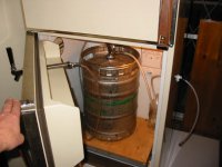
I saw those pictures of all those horns on the driveway. Looks like you are ready for a rock concert! I bet if you could turn the refrigerator into a speaker you would, eh?

I saw those pictures of all those horns on the driveway. Looks like you are ready for a rock concert! I bet if you could turn the refrigerator into a speaker you would, eh?
I have not found a significant difference in the types of caps or resistors. That being said I use polyester caps in the signal path, electrolytic for shunting.
I use perfect layer air coils chokes for signal path and usually air core for shunting unless they are huge and then I will resort to iron core. These are just a preference thing. As usual YMMV and everyone has an opinion.
I use perfect layer air coils chokes for signal path and usually air core for shunting unless they are huge and then I will resort to iron core. These are just a preference thing. As usual YMMV and everyone has an opinion.
I have not found a significant difference in the types of caps or resistors. That being said I use polyester caps in the signal path, electrolytic for shunting.
I use perfect layer air coils chokes for signal path and usually air core for shunting unless they are huge and then I will resort to iron core. These are just a preference thing. As usual YMMV and everyone has an opinion.
Cal, sounds like fun. I wished I lived close to you I'd love to come and see how it is done. I would love to be able to put together a fully loaded horn speaker some day. I love your 3 way A7s. The best pair of speakers I have ever sat in front of so far was a pair of A7 Voice of the Theatre speakers. I could be happy for the rest of my life sitting right if front of them. I was trying to trade a preamp for some horns when someone offered me this full range Braun L-910 German Studio Monitor. After listening to it I couldn't pass it up. It has a "horn-like" sound because of the directional mids. Once recapped I think it is going to sing and I wanted a DIY project to get my hand dirty. All I am capable right now is swapping parts.
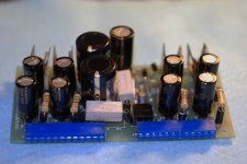
subsequently I have sat and listened to a lot of different caps and there are only subtle differences but what I say is that one boutique cap is nominal but all boutique caps can be phenomenal. I will say though that the type of cap is more different then the brand. The Russian PIO are a steal for the price and oil caps or difilms in a preamp really have a unique sound to me. I never heard truly extended highs until my friend with the A7 VOTs put a Mundorf SIO bypass cap into his pre, which had the 10uf Mcaps as coupling caps. The 2 (.68uf SIO) cost $100. The 2 (10uf K75-10s) difilm PIOs from Russia that I ordered cost me $11 for both. A 10uf Jensen of equal value would cost you $240 for 2. I certainly wouldn't go spending $100s of dollars on a single cap but my favourite combination is metallized polypropylene with oils - both can be reasonably priced. I guess I am at an age where if I want to spend about $300 in parts to restore 2 legendary vintage speakers its not that big of a deal. Still, I'd take a Blackgate any day over any other cap so far - worth every penny. This is the power supply to my preamp with 9 Blackgates. The 2 main Power caps are Mundorf but I finally tracked down a 4.7uf Blackgate to replace that last pesky little Elna left on the board
Attachments
18 ga??? The point being, you should meet my brother in law, who also knows what refrigeration is for...
Sorry no comment on fancy caps except electrolytics do murder hi freq transients.
Well, shows you how much I know about wire, which was the point of my inquiry. I just assumed they made an 18 gauge. Looks like 16 it is an if they don't make 16 then 14. I know they make 14 I have bought that one before. What wire would you use?
As far as capacitors killing high frequency transients that's probably a comment for someone who is smarter then me.
I just like how pretty they look.Yes they make 18 ga. I usually use 16 ga. inside the cabinet unless it's a small speaker then 18. Any larger and you run the risk of overheating the components when soldering the XO. Remember these are really short runs so it's hard to worry about this when there are so many other things to consider.
10, 12, 14, 16, 18, 22, 24 and CAT 5 are the gauges I have on hand.
10, 12, 14, 16, 18, 22, 24 and CAT 5 are the gauges I have on hand.
Yes they make 18 ga. I usually use 16 ga. inside the cabinet unless it's a small speaker then 18. Any larger and you run the risk of overheating the components when soldering the XO. Remember these are really short runs so it's hard to worry about this when there are so many other things to consider.
10, 12, 14, 16, 18, 22, 24 and CAT 5 are the gauges I have on hand.
Well I am off to Home Depot for some wire & maybe some new Roxul to re-stuff the cabinets but the old stuff should be fine right? I am just worried about dust but that stuff ain't too cheap for stuffin. I am waiting for my caps from russia but I will order some new 5-way connectors on Monday and start with the lead in wire to the capacitors. Thanks for your input Cal. I will post pics along the way for those of you who would like to see some sexy Russian caps in a box.
Difference in Values
I managed to get the second cabinet opened and it is interesting to see that there appears to be some differences. One of these speakers must have had some repairs made but all the capacitors are German. Considering that there are some sort of film caps in the first set of crossovers I am willing to bet that they are not original caps. Even still there are more discrepancies then just there. There is a 16.5uf vs 13.6uf (Where the films caps reside) on one crossover and a 40uf vs a 48uf difference on another. I kept hearing a slight bit of static in one speaker that was intermittent and this pair of caps might be the reason why. One of these looks dried out to me - either that or there is soldering resin all over it? These might be significant value differences, certainly 8uf is a significant difference. I already planned my restoration around the first set of values though I could settle the 40uf vs 48uf difference. Does anyone have an opinion on which might be the better value to use if my other values are 4.7uf, 14.7uf, & 80uf? How about I split the difference at 44.7?
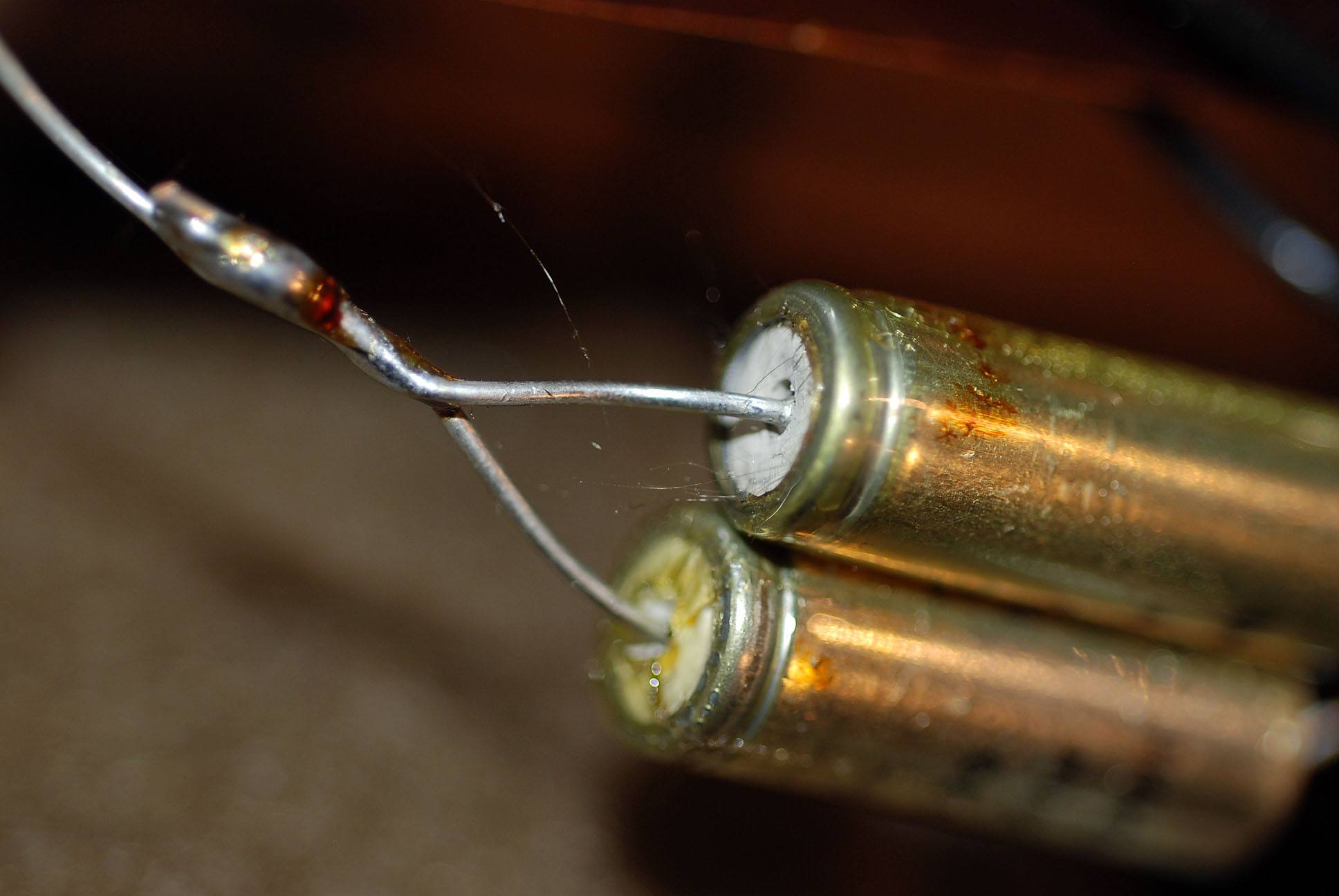
I managed to get the second cabinet opened and it is interesting to see that there appears to be some differences. One of these speakers must have had some repairs made but all the capacitors are German. Considering that there are some sort of film caps in the first set of crossovers I am willing to bet that they are not original caps. Even still there are more discrepancies then just there. There is a 16.5uf vs 13.6uf (Where the films caps reside) on one crossover and a 40uf vs a 48uf difference on another. I kept hearing a slight bit of static in one speaker that was intermittent and this pair of caps might be the reason why. One of these looks dried out to me - either that or there is soldering resin all over it? These might be significant value differences, certainly 8uf is a significant difference. I already planned my restoration around the first set of values though I could settle the 40uf vs 48uf difference. Does anyone have an opinion on which might be the better value to use if my other values are 4.7uf, 14.7uf, & 80uf? How about I split the difference at 44.7?
Attachments

- Status
- This old topic is closed. If you want to reopen this topic, contact a moderator using the "Report Post" button.
- Home
- Loudspeakers
- Full Range
- Choosing wire for crossover capacitor network