This is a split of from this thread:
http://www.diyaudio.com/forums/full-range/205403-looking-ideas-center-channel.html
It is using an alpair 10 version 2.
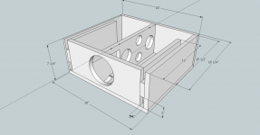
So this is what I have come up with. It is obviously inspired by the excellent work of Dave and others who have come up with a gambit of onken style designs. The simulations I can run cannot specifically model onken style, so please take a look at what I came up with.
.75 cu ft net (approximate; cross bracing not yet finalized)
4 vents .75" by 2" tall
F3 41.9 hz
F6 36 hz
vent velocity 11 m/s max at 38 hz
Please take a look and tell me what you think
Thanks in advance and thanks for having all the excellent content online.
103 db at 35 watts
http://www.diyaudio.com/forums/full-range/205403-looking-ideas-center-channel.html
It is using an alpair 10 version 2.
So this is what I have come up with. It is obviously inspired by the excellent work of Dave and others who have come up with a gambit of onken style designs. The simulations I can run cannot specifically model onken style, so please take a look at what I came up with.
.75 cu ft net (approximate; cross bracing not yet finalized)
4 vents .75" by 2" tall
F3 41.9 hz
F6 36 hz
vent velocity 11 m/s max at 38 hz
Please take a look and tell me what you think
Thanks in advance and thanks for having all the excellent content online.
103 db at 35 watts
Attachments
Shortening the vents to 9 inches seems to give a 1 or 2 db bump in the 60 hz region with a slightly sharper roll off...very slight. With the alpair 10 rise in response from 220 hz down to 80 hz would that bump cause any "mudiness"?
I am not using a stand alone sub, although I do have subs built in to the DefTechs I'm using for mains. I have them tuned for music as I listen to a lot of music. That's why I was going for as flat as possible.
I am not using a stand alone sub, although I do have subs built in to the DefTechs I'm using for mains. I have them tuned for music as I listen to a lot of music. That's why I was going for as flat as possible.
WinISD Pro does a pretty good job of multiple vents, but can't factor in the vent's end correction for shelf vents, so tuning will be a bit lower than it can predict.
Since the pipe harmonics of such long vents will comb filter with the driver's mids if not damped and tuning was a bit below the driver's published Fs when a maximally flat response dictates one above Fs; I shortened the vent to tune it to this spec since its measured Fs isn't available, 'killing two birds with one stone' by reducing the possibility of audible vent distortion and allowing for a bit of Fs error/thermal power compression, which usually means a higher than published spec/increased effective Qts.
IME, my alignment will be closer to maximally flat than yours, but acoustically the difference may not be obviously audible due to room conditions and frankly, probably not the best to use, but all I can do is comment on the app as presented.
For sure, you'll need to run the CC as 'small' for movies, so except for the potential vent pipe harmonic distortion issue, all the rest will be rolled off enough to be moot, hence my suggestion to shorten them. All things considered then, seems like a sealed alignment would be best overall.
GM
Nice box drawing. I'm jelouse of you guys who can do this. What program is that anyways?
looks like Googles ketchup to me
Yep google sketchup. Free to download and amazingly intuitive. Once you use it a few times you will be able to draw simple renderings like mine faster than you can by hand. Really.
GM...As I understand comb filtering (and I barely do) it has to do with the interaction between two drivers at higher frequencies and the distance at which they are placed introducing audible artifacts. While I only have one driver I would assume that the vents could be considered additional drivers as they are acoustically coupled to the outside of the box.
Can I assume that this interaction is what you are referring to? If I'm thinking correctly the port resonance at 12" long would be 1129 hz and at 9" would be 1507 hz. The spacing between the vent and the center of the driver is about 8 1/2" which is very close to your 9" reccomendation.
Am I drawing a corellation here and if so could I rectify this by moving the vents closer to the driver thereby significantly raising the frequency of the comb filtering effect?
I do want the low frequency extension that vented designs allow. Would venting to the rear effectively take comb filtering out of the equation?
P.S. I'm getting a little out of my depth here so go easy on me. I'm just trying to get a better grip on your comments.
Thanks in advance, Mike
Well, between two sound sources that are acoustically out of sync, which causes a ‘saw-tooth’ shaped response.
The acoustical conditions at a pipe/duct terminus are such that it can be modeled as a rigid piston same as a driver, so local boundary conditions are the same.
Yes, this is what I’m referring to and more since the vent is a half WL resonator, so can also modulate the driver from the backside: Resonances of open air columns
To the first approximation then, your math is off by a factor of two, but there’s the terminus end corrections to factor in as well as the impact of coupling to the air mass inside the cab, which further lowers the vent’s harmonic structure.
As fate would have it though, I did a quick sim using MJK’s old MathCad software and it appears your driver/cab is a typical ‘one note’ reflex with the long vent merely putting a so-so deep notch out around 800 Hz and my short vent flattening it out.
I’m so use to designing TLs, MLTLs that I didn’t give your cab’s driver/vent spacing any thought plus it will need a high pass filter, but being a CC, it’s best to keep the vents close if the listening position [LP] is more than one person wide just in case.
Regardless, the software I’m using doesn’t account for exterior comb filtering, only the vent system modulating the driver from within. Indeed, most calculators assumes the vent and driver output is all coming from the same point in space to keep the math simple.
Understood and why my responses are a bit more explanatory than I would normally give on this type of design.
You’re welcome!
GM
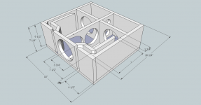
Revised
This is the revised plan. I have gone down to 2 vents for ease of construction. My goal was to get the vents as close as possible to the driver as well as tune slightly higher. The vent length is not set in stone and can be changed based on more expert eyes opinion. I used BBP6 this time and came up with this:
.75 cu ft
Fb 53 hz
F3 47 hz
vents are 6.5" x .75" x 11"
The bracing is not set in stone either as they do butt right up to the vents in the drawing. This could act as an extension of the vent.
This design is fiance' approved with the appropriate wood treatment for the front 3 panels.
Please take a look and critique.
Thanks, Mike
Attachments
This is the revised plan. I have gone down to 2 vents for ease of construction. My goal was to get the vents as close as possible to the driver as well as tune slightly higher. The vent length is not set in stone and can be changed based on more expert eyes opinion. I used BBP6 this time and came up with this:
.75 cu ft
Fb 53 hz
F3 47 hz
vents are 6.5" x .75" x 11"
The bracing is not set in stone either as they do butt right up to the vents in the drawing. This could act as an extension of the vent.
This design is fiance' approved with the appropriate wood treatment for the front 3 panels.
Please take a look and critique.
Thanks, Mike
take some training in animal behavioral studies - where's the cheese?
")
looks cute
These vents simplify construction?! Regardless, they are likely to be resistive in nature due to both being a high aspect ratio and with multiple bends, so no clue what their tuning will be, though AkAbak might can sim them.
I’m not keen on the bracing either. At minimum, I would use a couple of dowels in lieu of the restrictive ‘window’ cross bracing.
GM
I’m not keen on the bracing either. At minimum, I would use a couple of dowels in lieu of the restrictive ‘window’ cross bracing.
GM
- Status
- This old topic is closed. If you want to reopen this topic, contact a moderator using the "Report Post" button.
- Home
- Loudspeakers
- Full Range
- Center design: please critique