I was looking for a speaker project so I could learn a bit about carpentry and after some interaction with Scott Lindgren, I decided to give Silbury a go, though I was a bit trepidatious. Silbury is a "Double-mouth back-horn with Olson style manifold-expansion named for Neolithic British sites", plans and support are available from Scott at wodendesign.com. I found very little about these speakers on the web and it definitely wasn't as difficult as I had feared, so I decided to post a few pictures to encourage others of similar skills to consider it.
I should mention that there is another thread on a similarish build where you can see how a skilled carpenter approached the challenge http://www.diyaudio.com/forums/full-range/104879-mikasa-next-11.html It should be redundant for me to state that no similar skills are contained in these posts, but I did learn a quite a bit and the techniques deployed by ArtsyAllen no longer seem like evidence of alien interaction.
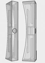
I've attached a picture from the website of Silbury, it's about 6 foot tall and has a nice swooping back that apparently is important sonically, but I think it deserves to be in there for looks alone.
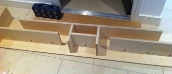
Silbury uses the MarkAudio 10.2 driver, the centre front is a compression chamber and then there is a horn section behind for more of that enjoyable bass. Construction wise the front, top, bottom and sides appeared easy to glue and clamp together (if I bought enough clamps). However, the vertical boards that form the back and the two internal walls seemed to me much less obvious.
I should mention that there is another thread on a similarish build where you can see how a skilled carpenter approached the challenge http://www.diyaudio.com/forums/full-range/104879-mikasa-next-11.html It should be redundant for me to state that no similar skills are contained in these posts, but I did learn a quite a bit and the techniques deployed by ArtsyAllen no longer seem like evidence of alien interaction.
I've attached a picture from the website of Silbury, it's about 6 foot tall and has a nice swooping back that apparently is important sonically, but I think it deserves to be in there for looks alone.
Silbury uses the MarkAudio 10.2 driver, the centre front is a compression chamber and then there is a horn section behind for more of that enjoyable bass. Construction wise the front, top, bottom and sides appeared easy to glue and clamp together (if I bought enough clamps). However, the vertical boards that form the back and the two internal walls seemed to me much less obvious.
Attachments
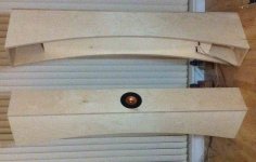
I'll come back to the internal walls in a while, first I'll describe making the curved back. If you're also inexperienced at woodworking, you should have the cutting done for you. My local B&Q doesn't stock Baltic Birch as the demand is so low, I eventually found a cabinet maker who would do the cutting for me on his table saw, I was really impressed with the accuracy. The cost was not for the faint hearted (€180 for three sheets of 2440x1220 of 18 mm BB, another €50 for material collection and cutting. Ouch. Drivers were €99 each.)
One method mentioned elsewhere for a curved back is to draw your curve, jigsaw as close as you dare and then get sanding. This did not sound like fun, especially as I live in an apartment so lots of fine dust is not on.
I used a wood router and a stencil instead, it produces a lot small shavings, but they fall to the ground and are easy to hoover up.
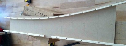
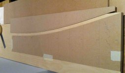
I calculated the points of the curve every 100 mm and marked them on the piece of 9 mm thick MDF I was going to use as a stencil. Then I got a piece of 20 x 10 mm^2 pine and screwed it down to the MDF, bending the wood at each step so it matched the calculated points. This thickness of wood just about bent sufficiently, and was thick enough to pass screws through. I used a jigsaw to get close to the guide and then used a flush trim bit on the router to make it smooth. Next step is to duplicate the stencil, one lesson I learned on the project is that if your attention wanders while using a router it will take its chance to wreak non-reversible havoc upon your precious wood. I kept hitting crtl-Z but no good.
I found beginning a pass through the wood tricky, I'm not sure what I should have done differently, once the router gets going along the stencil though, it's plain sailing. Sand the edges afterwards and the curves are done.
One method mentioned elsewhere for a curved back is to draw your curve, jigsaw as close as you dare and then get sanding. This did not sound like fun, especially as I live in an apartment so lots of fine dust is not on.
I used a wood router and a stencil instead, it produces a lot small shavings, but they fall to the ground and are easy to hoover up.
I calculated the points of the curve every 100 mm and marked them on the piece of 9 mm thick MDF I was going to use as a stencil. Then I got a piece of 20 x 10 mm^2 pine and screwed it down to the MDF, bending the wood at each step so it matched the calculated points. This thickness of wood just about bent sufficiently, and was thick enough to pass screws through. I used a jigsaw to get close to the guide and then used a flush trim bit on the router to make it smooth. Next step is to duplicate the stencil, one lesson I learned on the project is that if your attention wanders while using a router it will take its chance to wreak non-reversible havoc upon your precious wood. I kept hitting crtl-Z but no good.
I found beginning a pass through the wood tricky, I'm not sure what I should have done differently, once the router gets going along the stencil though, it's plain sailing. Sand the edges afterwards and the curves are done.
Attachments
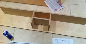
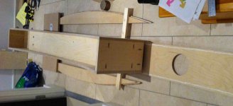
Despite Scott hating them, I used pocket screws for the construction, from a company called Kreg, check youtube for their videos. You must consider whether you want them visible afterwards, I had them internal except for the top and bottom pieces.
Attachments
The curved side pieces, not back, appear to be more artifice than anything
else, and could easily be replaced by two straight V cuts, its not critical.
Actually they are not. Ron Clarke brought this design element to horns. It helps the wavefront coming out of a high aspect ratio rectangular horn mouth more easily approach the optimal spherical shape.
dave
OK next to my least favourite part of the construction path I chose.
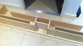
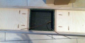
Once the internal parts are in and dried, you must check that the back and the two inner layers are at the same height, preferably the middle piece slightly higher, sand down as appropriate. Then glue up and attach the second side piece. This is the part of the build that was least satisfying as I couldn't check the fit of the hidden internal layer, maybe there was a gap? I did a 'damp' run by applying dabs of glue all along this piece and putting it together then checking was the glue squashed. It should have been ok but I still don't like it. ArtsyAllen used box joints in his built so he could know things were ok. Also, the screws do shift the wood a little, it's a small amount but visible. And worrying.
Once the internal parts are in and dried, you must check that the back and the two inner layers are at the same height, preferably the middle piece slightly higher, sand down as appropriate. Then glue up and attach the second side piece. This is the part of the build that was least satisfying as I couldn't check the fit of the hidden internal layer, maybe there was a gap? I did a 'damp' run by applying dabs of glue all along this piece and putting it together then checking was the glue squashed. It should have been ok but I still don't like it. ArtsyAllen used box joints in his built so he could know things were ok. Also, the screws do shift the wood a little, it's a small amount but visible. And worrying.
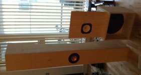
OK from here it's plain sailing.... or should have been. Route out the rebates for the driver, only make sure you use the dimensions for the 10.2 driver, not the gen 1 driver, I know this idiot who .... where's the smilie for punching myself in the face?
Line the inside of the compression chamber with damping material, I couldn't get anything from the car stores so I bought some online, it was adhesive backed so it was super simple to insert.
Then glue the front on and wait.
Line the inside of the compression chamber with damping material, I couldn't get anything from the car stores so I bought some online, it was adhesive backed so it was super simple to insert.
Then glue the front on and wait.
Attachments
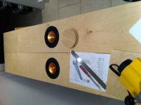
MarkAudio gave instructions on how to install the driver, basically mark the holes with a 4 mm drill bit, then drill 2.8 mm pilot holes, make sure the driver is taped down when marking the holes, the 4 mm drill bit will move the driver otherwise. MarkAudio suggests having the driver upside down when marking with the 4 mm drill, so no slip up can destroy the metal cone. Obviously the driver is somewhere else when the pilot holes are being drilled. Then use the included screws to evenly insert the driver.
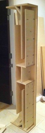
After all your efforts you now have a pair of elegant backhorns!
After all your efforts you now have a pair of elegant backhorns!
Attachments
Route out the rebates for the driver, only make sure you use the dimensions for the 10.2 driver, not the gen 1 driver
The 10.2, at least here is North America, comes with the bezel cover loose, you can use it or not. Without it the rebate is the same as the gen 1 driver. This is how i choose to use them (and sell them). I do not like the raised circular rim that the bezel cover creates. Any additional stiffness engendered by the bezel becomes moot (at least mostly) once the driver is attached to the baffle. Using the driver sans decorative bezel cover also means the rebate is not as deep and leaves more meat to support the driver.
dave
After all your efforts you now have a pair of elegant backhorns!
Do let us know how they sound. And if you can send me some hi-rez photos for the website & documents.
dave
Sooo, little bits and pieces...
The speakers are really heavy, I'm guessing between 40 and 50 kg each! And there's this delicate piece you can't touch right where I want to put my hip! I ended up using a hand trolley to move them around.
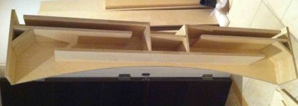
There's a couple of deadspaces, I used dried sand to fill these.
There are a pair of 45 degree pieces at the horn mouths, I ended up using a rasp and sander to make these. I'm pleased with neither my technique nor the outcome") If you don't have a mitre saw I suggest using steps of material to form this part might be good.
If you don't have a mitre saw I suggest using steps of material to form this part might be good.
The visual impact of the horns isn't simple, the front view is very slim and elegant and the white of the unfinished (so far) BB, with the black and copper of the driver looks fantastic to my eyes. Then if you see them from the side, the depth is striking and they do seem quite monumental, in line with their name.
The attached picture might explain a little, here's a Silbury with the previous height of my carpentry achievements, a 15 inch woofer in a H frame. Technically the H-frame and open baffle are smaller, but they're way more obtrusive visually and inexpressibly ugly (to me). The larger Silbury has half its mass above the driver and so crowds the space less. I wasn't using the space above my H-frame and OB for anything anyway.
The speakers are really heavy, I'm guessing between 40 and 50 kg each! And there's this delicate piece you can't touch right where I want to put my hip! I ended up using a hand trolley to move them around.
There's a couple of deadspaces, I used dried sand to fill these.
There are a pair of 45 degree pieces at the horn mouths, I ended up using a rasp and sander to make these. I'm pleased with neither my technique nor the outcome
If you don't have a mitre saw I suggest using steps of material to form this part might be good. The visual impact of the horns isn't simple, the front view is very slim and elegant and the white of the unfinished (so far) BB, with the black and copper of the driver looks fantastic to my eyes. Then if you see them from the side, the depth is striking and they do seem quite monumental, in line with their name.
The attached picture might explain a little, here's a Silbury with the previous height of my carpentry achievements, a 15 inch woofer in a H frame. Technically the H-frame and open baffle are smaller, but they're way more obtrusive visually and inexpressibly ugly (to me). The larger Silbury has half its mass above the driver and so crowds the space less. I wasn't using the space above my H-frame and OB for anything anyway.
Attachments
There are a pair of 45 degree pieces at the horn mouths, I ended up using a rasp and sander to make these. I'm pleased with neither my technique nor the outcome
The visual impact of the horns isn't simple, the front view is very slim and elegant and the white of the unfinished (so far) BB, with the black and copper of the driver looks fantastic to my eyes. Then if you see them from the side, the depth is striking and they do seem quite monumental, in line with their name.
The attached picture might explain a little, here's a Silbury with the previous height of my carpentry achievements, a 15 inch woofer in a H frame. Technically the H-frame and open baffle are smaller, but they're way more obtrusive visually and inexpressibly ugly (to me). The larger Silbury has half its mass above the driver and so crowds the space less. I wasn't using the space above my H-frame and OB for anything anyway.
I well know, i lived with Bernies Victor for a month or more (very similar to Silbury, a bit wider, and for FE166En). The tall slim shape is very elegant,
dave
Do let us know how they sound. And if you can send me some hi-rez photos for the website & documents.
dave
I just have my phone for pictures so I'll see if I can cadge a proper camera at work. Not too good though as there's still lots of rough edges. I've ordered a scraper kit for finishing. Until that gets here I'll be doing some listening.. and enjoying an obstruction free hallway.
Sound.... hmmmm. I have to laugh at how easy I find it to explain what I experience visually but soundwise I'm pretty tongue tied. The SNR is better than the FE166En in OB, i.e. I can distinguish low level sounds that I hadn't heard before, and I find lyrics more intelligible. The main experience I have though is that the sound is really immersive and involving, and much more so with my KT88 amps than my Burning Amps, no idea why this would be so. Scott said I could use more stuffing to attenuate the bass, and I can see why some would do so, it is powerful. The h-frame that's getting replaced was tuned to 40 Hz and had 150 W or so available from the amp (96 dB efficiency), this bass feels more powerful and impactful, it might not be accurate with current stuffing but for the type of music I listen to mostly, this is super. I think you would not want a small room to house these, about 3 m away or more seems best, at 9 m away the sound hasn't degraded, which is odd to me.
I'm interested in your listening impressions over time, as the alpair drivers break in and you become more aware of the differences between these and your open baffles.
I'll try but these things are so personal.... one thing that does seem absent so far is the occasional unpleasant sound the Fostex emitted, I think this is what people refer to as 'Fostex shout' but I could have that wrong. Nothing like that so far from the 10.2
motosapien - all credit to the designer and the nice building material, the snaps look like poor quality camera output, in fact it's Vaseline on the lens to hide the rough edges
Actually they are not. Ron Clarke brought this design element to horns.
It helps the wavefront coming out of a high aspect ratio rectangular
horn mouth more easily approach the optimal spherical shape.
dave
Hi, sorry but thats pure marketing speak tosh, it does nothing of the sort in any effective sense, rgds, sreten.
The expansion is allegedly "Hypex" whatever than means, but properly tapered expansions will work better.
The design is simplistic, with parallel sections, it could easily be modified for 3 section tapers, YMMV.
Last edited:
- Status
- This old topic is closed. If you want to reopen this topic, contact a moderator using the "Report Post" button.
- Home
- Loudspeakers
- Full Range
- Novice build of Silbury