Acually the design is the reason for the boominess, the throat area has too be in the expotenial relationship to the mouth area. when looking at your design the dimentions right after the throat are out of proportion, here is a tip. make a scaled drawing with a strait center line draw in your throat area and then draw in your actual measurments and you will see that the horn is out of proportion to the mouth of the horn. There is a formula that can be used. please see here!
Design of a Back Loaded Exponential Horn By Martin J. King, 7/01/08
Design of a Back Loaded Exponential Horn By Martin J. King, 7/01/08
Acually the design is the reason for the boominess, the throat area has too be in the expotenial relationship to the mouth area... Design of a Back Loaded Exponential Horn
Exponential is not the be-all & end-all of horns. Horn-space is MUCH larger than that. Martin King's software has been one of the of the keys to opening up a much larger space to exploration.
Tom has used MJK to design the horn, and that software is pretty good at simming a design.
A horn will not willy nilly work with any driver, just like any other enclosure they are designed fro a specific driver, and sometimes you get lucky and another will work passably well.
dave
Dave,
I suppose I should know this but why do the FR drivers we use seem to (when the Q is low) frequently function well in our horn designs?
A word on my design process. I start with Martin's published equations for calculating the length and shape and mouth of the horn (edit: and the CC). I do all this on paper with a good old fashioned scientific calculator. I actually only use Martin's software when I am trying to calculate the diameter of the horn at certain distances on the line. I then go back to paper and pencil and draw the design out on graph paper keeping in mind parameters I want to achieve such as width, depth and height of enclosure as well as listening height of the driver. Once I have a design that works spatially (and this is the trick of speaker design, fitting what you want physics wise in the box in which you want it to reside) then and only then do I begin the measurements of the drawing to start plugging numbers in to MJK's simulation software, the results of which give me the information I need to tweak the design and compression chamber to achieve the results I am after.
The reason I laid this out Dave, is I wanted people to understand that you don't design a speaker with MJK software. What you had written above indicates that this is possible. I argue that if you don't know or understand the math and physics, you will never design a speaker that sounds anything better than just mediocre or less, and trust me, my early designs that I built sounded just that. I do in fact use Martin's extensive research as my starting point and without him I would have very little understanding of what I am doing. That said, there is a huge amount of creativity and sometimes even a little shot in the dark magic that goes in to a speaker design.
Buschhorn,
You are in fact wrong. How do you think I design these things? Throwing a dart at the dart board? Martin's math is what I start all my designs with. The throat to mouth relationship on this horn is exactly as it should be according to the math. How do you get that they are out of whack? Should I post my math? Not mention, did you bother to look at the other sims? They look excellent. That driver that shows the bass peaks is just not suitable for this horn with this CC. In fact, I suspect that the CC is the complete reason for the boominess. I am not going to bother to sim it with the CC adjusted but I could smooth it by decreasing the size of the CC I am sure. I am not sure if you realize this but the CC is the only thing you change on a horn to adjust for a driver. a 37 Hz horn is a 37 Hz horn is a 37 Hz horn. The horn profile doesn't change for drivers unless you are trying to tune the horn at a different frequency.
Tom
I suppose I should know this but why do the FR drivers we use seem to (when the Q is low) frequently function well in our horn designs?
A word on my design process. I start with Martin's published equations for calculating the length and shape and mouth of the horn (edit: and the CC). I do all this on paper with a good old fashioned scientific calculator. I actually only use Martin's software when I am trying to calculate the diameter of the horn at certain distances on the line. I then go back to paper and pencil and draw the design out on graph paper keeping in mind parameters I want to achieve such as width, depth and height of enclosure as well as listening height of the driver. Once I have a design that works spatially (and this is the trick of speaker design, fitting what you want physics wise in the box in which you want it to reside) then and only then do I begin the measurements of the drawing to start plugging numbers in to MJK's simulation software, the results of which give me the information I need to tweak the design and compression chamber to achieve the results I am after.
The reason I laid this out Dave, is I wanted people to understand that you don't design a speaker with MJK software. What you had written above indicates that this is possible. I argue that if you don't know or understand the math and physics, you will never design a speaker that sounds anything better than just mediocre or less, and trust me, my early designs that I built sounded just that. I do in fact use Martin's extensive research as my starting point and without him I would have very little understanding of what I am doing. That said, there is a huge amount of creativity and sometimes even a little shot in the dark magic that goes in to a speaker design.
Acually the design is the reason for the boominess, the throat area has too be in the expotenial relationship to the mouth area. when looking at your design the dimentions right after the throat are out of proportion, here is a tip. make a scaled drawing with a strait center line draw in your throat area and then draw in your actual measurments and you will see that the horn is out of proportion to the mouth of the horn. There is a formula that can be used. please see here!
Design of a Back Loaded Exponential Horn By Martin J. King, 7/01/08
Buschhorn,
You are in fact wrong. How do you think I design these things? Throwing a dart at the dart board? Martin's math is what I start all my designs with. The throat to mouth relationship on this horn is exactly as it should be according to the math. How do you get that they are out of whack? Should I post my math? Not mention, did you bother to look at the other sims? They look excellent. That driver that shows the bass peaks is just not suitable for this horn with this CC. In fact, I suspect that the CC is the complete reason for the boominess. I am not going to bother to sim it with the CC adjusted but I could smooth it by decreasing the size of the CC I am sure. I am not sure if you realize this but the CC is the only thing you change on a horn to adjust for a driver. a 37 Hz horn is a 37 Hz horn is a 37 Hz horn. The horn profile doesn't change for drivers unless you are trying to tune the horn at a different frequency.
Tom
Last edited:
Harderror,
Thank you very much for running the sim on the FW208N. Is that boominess caused by too low a Qts, too low an Fs, or is it more complicated than that?
Sorry I didn't reply to you specifically. Read my posts just before this one to get an idea whats wrong. I suspect its just a CC (compression chamber) size problem and has nothing to do with the Q or the FS of the driver. The nice thing about a horn is that they are very forgiving of these specific things. I said I wouldn't re-sim it with an adjusted CC but I think I will just to see if it helps. If it does, then with the way I designed this box, you can adjust your CC quite a bit in either direction. Let me run upstairs and I will take a look at the numbers.
Tom
Tom,
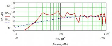
Are you sure the T/S parameters you used to create the SPL curves in Post #19 are correct. The dashed blue curve, driver infinite baffle response, does not look right for a low Qts driver. The SPL at 1 kHz looks very low and the hump around the driver fs looks more typical of a driver with a Qts valius of 1.2. I think this is what produced the boomy BLH response.
Martin
Okay, I just simmed it again with different CC sizes. I was wrong in my assumption. I have to retreat and say I am not sure why this driver is not working well but I don't believe the Qts is the problem. I think the Fs as you stated may have a little to do with it. This is a 37 Hz exponential horn. That is a driver with a free air resonance of 29 Hz. The horn is likely tuned too high for this driver and just as with a BR box displays a boominess in a particular frequency range when tuned too far above the Fs of the driver. That's my best guess at it. Anyone else want to take a stab at the full reasoning? Dave, Chris, Gm, Scott?
Tom
Tom
Tom,
Are you sure the T/S parameters you used to create the SPL curves in Post #19 are correct. The dashed blue curve, driver infinite baffle response, does not look right for a low Qts driver. The SPL at 1 kHz looks very low and the hump around the driver fs looks more typical of a driver with a Qts valius of 1.2. I think this is what produced the boomy BLH response.
Martin
Thank you Martin for chiming in. No, I am not sure of those parameters. They are what was provided me. I thought the curve looked out of whack as well. So, if the T/S parameters are incorrect then all my stammering around in the dark here was in vain. Hehe, that's good to know because I hate it when I am totally befuddled by something. So what do you think is off on those parameters? I looked and looked around for a full set or a measured set on the interwebs but wasn't able to get any.
Tom
Thank you Martin for chiming in. No, I am not sure of those parameters. They are what was provided me. I thought the curve looked out of whack as well. So, if the T/S parameters are incorrect then all my stammering around in the dark here was in vain. Hehe, that's good to know because I hate it when I am totally befuddled by something. So what do you think is off on those parameters? I looked and looked around for a full set or a measured set on the interwebs but wasn't able to get any.
Tom,
My guess is the BL you entered is too low. Did you use the MathCad worksheets to check or complete the T/S parameters? If you have Vad then you can calculate BL using the appropriate MathCad worksheet. I think there is enough info to derive the T/S parameters not provided on the Fostex data sheet. If you cannot find independent measured results, this is the next best option.
Martin
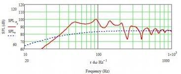
Hmm, I did use your BL sheet. Let me double check to see what numbers I used. I entered something wrong it seems. I don't know what though because as you stated my BL is coming back way different than it did the first time. Maybe I misread the results before. The IB response is more inline for what we were looking for. Thank you Martin. Now, we are still getting a wicked hump at 40 Hz but hang on (doing all of this in realtime). Okay, I was correct about the CC helping a great deal. I don't seem to be able to lose the 40 Hz hump but I can reduce or at least alter it through CC volume adjustment. Martin, as always, thank you for chiming in.
Tell me, is the 40 Hz hump a result of a horn that is tuned too high for the driver in question? Thanks!
Tom
Attachments
Harderror,
Thank you very much for running the sim on the FW208N. Is that boominess caused by too low a Qts, too low an Fs, or is it more complicated than that?
Well, due to my own error those initial results were off. Now, from the looks of it, that driver will work but you will have a pretty obvious 3-4 DB hump at 40 Hz. I think that could be tamed with stuffing but let me go check that. BTW, the sim I posted on the last post was with an enlarged CC. If you were to keep the CC the same size, the hump would be at 45 Hz. Adjusting stuffing could help but keep in mind if you stuff too densely you could affect the dynamics of the driver adversely and likewise if you don't stuff at all. I tend to just line all sides of the CC with batting but others claim they like the sound with actual stuffing in the CC. You can adjust things marginally as well by stuffing the first 1/3 of the line and or batting different areas down the line. I think the only way you are going to reduce that hump is through the adding of series resistance. 6 ohms gives a pretty acceptable curve. (See attached) The attached FR is the design as is with 6 ohm of series resistance added. That in theory could sound pretty good though it may be a touch unethical in Full Range circles.
So, coming full circle, yes, this design could work quite well with that driver. I hope to see someone try it as it could be interesting to have a true audiophile 2-way horn design that needs no subwoofer. In fact, I want to try it now. So many drivers, so little money.
Tom
Attachments
Last edited:
Tell me, is the 40 Hz hump a result of a horn that is tuned too high for the driver in question?
Tom,
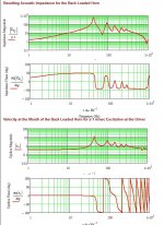
Can you post the acoustic impedance and the velocity ratio plots?
Martin
Tom,
Can you post the acoustic impedance and the velocity ratio plots?
Martin
Sure Martin. Here you go!
Tom
Attachments
Tom,
I think you need to look at this as two designs.
Below about 200 Hz you have a TL (or TQWT if you prefer) with several lightly damped standing wave resonances. These create the peaks in both the acoustic impedance and velocity ratio plots. The resonant behavior spills over into the SPL plot where you see peaks and dips. Adding stuffing will help reduce the Q of each peak.
Above about 200 Hz the acoustic impedance of the mouth is starting to damp the standing waves and couple the "horn" to the room efficiently. That and the offset of the driver in the coupling volume smooths the SPL response.
Now assuming you can live with the peaky-ness. The elevated response below 200 Hz is going to help with the baffle step issue. I think you will see benefits in the corner loaded part of the simulation.
Martin
Tom,
I think you need to look at this as two designs.
Below about 200 Hz you have a TL (or TQWT if you prefer) with several lightly damped standing wave resonances. These create the peaks in both the acoustic impedance and velocity ratio plots. The resonant behavior spills over into the SPL plot where you see peaks and dips. Adding stuffing will help reduce the Q of each peak.
Above about 200 Hz the acoustic impedance of the mouth is starting to damp the standing waves and couple the "horn" to the room efficiently. That and the offset of the driver in the coupling volume smooths the SPL response.
Now assuming you can live with the peaky-ness. The elevated response below 200 Hz is going to help with the baffle step issue. I think you will see benefits in the corner loaded part of the simulation.
Martin
Hey Martin, I sent you an email regarding my membership to your worksheets section. Thanks!
Tom
Tom,
I think you need to look at this as two designs.
Below about 200 Hz you have a TL (or TQWT if you prefer) with several lightly damped standing wave resonances. These create the peaks in both the acoustic impedance and velocity ratio plots. The resonant behavior spills over into the SPL plot where you see peaks and dips. Adding stuffing will help reduce the Q of each peak.
Above about 200 Hz the acoustic impedance of the mouth is starting to damp the standing waves and couple the "horn" to the room efficiently. That and the offset of the driver in the coupling volume smooths the SPL response.
Now assuming you can live with the peaky-ness. The elevated response below 200 Hz is going to help with the baffle step issue. I think you will see benefits in the corner loaded part of the simulation.
Martin
When I design a horn, I always make sure I am getting around a 4-6db lift so that baffle step is effectively dealt with. The thing that has me on this driver is that sharp peak at 40 or 45 Hz depending on the parameters of the CC. I guess I just wanted to understand why this particular driver looked to be 3 db higher at 40 than it is at 70. I now believe it's an impedance issue to some degree but the question still remains, what causes that sudden swoop up on the FR at that frequency. Do you believe that a speaker with a free air resonance of 29 Hz is peaking like that because the horn is tuned to 37 Hz or 45 Hz? I suppose it isn't that terribly important since the majority of the drivers I designed this enclosure for have a fairly smooth LF shoulder and don't do a quick peak just before dropping but understanding why seems like it would be helpful. Thanks again Martin!
Tom
Sorry guys I have been insanely busy! I am back at teaching and dealing with all my hobbies are time consuming. I recently started restoring a 1986 BMW R80RT motorcycle so that has taken up some of my time as well. I will try to get those plans out very soon. It shouldn't take more than an afternoon and maybe an evening to work it out. Maybe in the next ten days!
Tom
Tom
- Status
- This old topic is closed. If you want to reopen this topic, contact a moderator using the "Report Post" button.
- Home
- Loudspeakers
- Full Range
- New BLH for 8" drivers "The Blizzard"