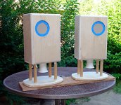
Finishing up a build using the Mark Audio CHR70 (first generation). It's a 9.6 liter BR enclosure tuned to around 50Hz. Will be a "tabletop radio" for my office. I plan to use a NAD 7240PE receiver to drive. After some listening I'd like to add some BSC to see what that does to the sound. I've used the receiver's loudness filter and that doesn't even do the trick for me.
I was hoping to make this simple and use a cheap passive line-level network like Rod Elliott's Baffle Step Compensation. Rod states "It is essential that the compensation circuit be driven from a low impedance source, and the load impedance should be reasonably high. There will be little error with loading above 20k, but basically the higher the impedance, the better. Opamp buffers at the input and output may be used if you cannot ensure that the source impedance is 100 ohms or less, and that the load impedance of the following stage is greater than 20k. My recommendation would be to use a buffer stage at the output with an input impedance of about 100k."
According to NAD specs for my 7240PE receiver the preamp output is 600 ohms and the amp input is 22,000 ohms. So the preamp output impedance looks to me to be too high. I'm not anywhere near being skilled enough to know what to do or to design a solution. I don't even know what it would do if I built the filter and hooked it up given the 600 ohm output impedance. Is there a way to make this work without building a power supply and using opamps?
I know an alternative is to build and tweak a filter at the loudspeaker level using inductors and resistors, my patience would probably be tested, not to mention the cost of several inductors of differing values (times two) to use for tweaking.
Anyone have a solution to modify the Elliott design to work with the NADs 600 ohm output impedance or other ideas?
Attachments
Thx for the link, dave.
I use the same circuit for my car FR ( on-dashboard) speakers as a midrange "notch-filter".
OK, but limited to max. -3dB only, and very low Q (= wide bandwidth...)
In front of the speaker, there are much better options... E.G. ,taming 2 seperate peaks with a passive line filter is simply impossible.
Joe
Thanks!Can't help with your BSC question but those are cool looking speakers.
I'll likely leave it exposed, but that depends on what they look like after I get some finish on them. Plan is for a dark blue painted finish and then make the port the same gold color as the drivers are. I figure I can wrap the bottom with some cool looking fabric if I need to.Do you intend to leave the port/horn exposed?
BTW the enclosures were originally going to be narrow baffle (what is now the side would have been the baffle) but the 2-inch port was the smallest port I could get PVC to form to. SO that increased the length and forced a change in the design. I think these will work better on the credenza anyway. I tried a smaller diameter PVC. Couldn't get the temperature right for bending/molding or maybe the PVC in the smaller diameter just wasn't stretchy enough. I'll add some detail in a post when I get them finished.
I think somewhere around -3db. That's why I like the idea of a variable filter.Hmm,
-6dB is never needed. Imagine the pot set at 50%... with 100Ohm "out" the circuit is working with 5,1kOHm effective "source resistance"....
Imho no problem with 600Ohm source resistance.
Thanks for the link. I designed 9.6 liters but with the damping (Monacor MDM-3 from MCM) probably somewhere closer to 10 liters and plan was tuned to 50Hz. From my WT3 test though it probably comes out to more like 45 Hz.
Listening now with a breadboarded version of the Rod Elliott circuit using his calculations for the value of the cap. Definitely on to something here. The overall sound is far more integrated now, but I need to evaluate with more source material before I make a final decision on where to put the "marks on the dial." So far I've found that using between -2dB and -4dB works well. More to come.
BTW I tried the Joppa version and added the optional C1 cap. Didn't need that at all--or maybe my calculations were off. Added a treble "ring" to the sound that I found to be fatiguing.
BTW I tried the Joppa version and added the optional C1 cap. Didn't need that at all--or maybe my calculations were off. Added a treble "ring" to the sound that I found to be fatiguing.
Without going back and reading the article, the caps purpose is to take the circuit out at high frequencies, lifting the top of a speaker that is a bit soft on the top. CHR certainly doesn't need help there.
dave
Yeah, everything I listened to came off as a little bit obnoxious with the top lifted.
I also used The Edge to determine f3 and that resulted in a much lower f3, 240Hz from The Edge vs. 442Hz using Rod Elliott's formula. I built that 240Hz f3 circuit, but after a few minutes of listening it was obvious that the higher 442Hz f3 resulted in an overall sound that I liked better. When I have time I'll hook up the laptop and do measurements of the drivers in the enclosures to see if what I'm hearing matches up with empirical data. What I'm hearing now sounds pretty good for the $ I've spent.
- Status
- This old topic is closed. If you want to reopen this topic, contact a moderator using the "Report Post" button.
- Home
- Loudspeakers
- Full Range
- Line-Level Passive BSC for CHR70