This thread is about a circuit used in those speakers: Audiophile Tube Amps and Tube Gear from DECWARE
Discussed in that thread: http://www.diyaudio.com/forums/full-range/180185-new-fr-ob-driver-decware.html
It is something new to me and I am curious. How does it work?
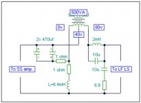
It seems to me that it has something in common with the T-Bass cirquit found here: http://www.diyaudio.com/forums/full-range/130679-t-bass-drive-ob-lf-drivers.html and attached below
Both alter the conductivity of an inductance through current/voltage applied to it's middle point or through magnetic inductance induced by coul - the last is the case that I'm interested in... and probably not only me...
Apart from the pure theoretical explanation it is also interesting for me whether it is necessary the two inductances to interact with the driver's permanent magnet or it can be another permanent magnet or a core or two air cored transformers.
I understand it might be naive, but if it is something useful and relatively easy to understand and DIY why not get into it's knowledge.
Best Regards!
Discussed in that thread: http://www.diyaudio.com/forums/full-range/180185-new-fr-ob-driver-decware.html
It is something new to me and I am curious. How does it work?
It seems to me that it has something in common with the T-Bass cirquit found here: http://www.diyaudio.com/forums/full-range/130679-t-bass-drive-ob-lf-drivers.html and attached below
Both alter the conductivity of an inductance through current/voltage applied to it's middle point or through magnetic inductance induced by coul - the last is the case that I'm interested in... and probably not only me...
Apart from the pure theoretical explanation it is also interesting for me whether it is necessary the two inductances to interact with the driver's permanent magnet or it can be another permanent magnet or a core or two air cored transformers.
I understand it might be naive, but if it is something useful and relatively easy to understand and DIY why not get into it's knowledge.
Best Regards!
Attachments
i havent had time enough to look at the links you provided (im just off tv shopping) but i believe you are asking about mutual coupling between coils, and the use of a trannie as a mutually coupled inductor.
i dont usually use trannies in this way, so i cannot really say much about the subject, other than i only know of this technique being used for a very large inductance value, for a sub passive filter for example. im sure it will work in your application, if you design correctly; other than that i dont see/know what possible benefits it would have in a 'non subwoofer' application.
many some others would contribute, and fill in the blanks, as there are plenty with similar and greater experience than i.
BUMP!
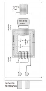
It definitely has lots to do with core saturation. As we know inductances with saturated core become conductors.
Bigger load on the secondary winding means leser current draw from the primary and vice versa.
The current draw is altered through load (resistance) that means that the load exhibited by the secondary winding alters the resistance of the primary.
In that case the amount of current drawn by the loading resistance in paralel with the secontady winding is proportional to the current fed to the primary.
The bigger the frequency the more saturation of the core the bigger the current fed to the loading resistor, the bigger the current demand to the primary winding the lesser is it's resistance...
But all this in the last paragraph happens in some curved shape (impedance graph) related not so much to the initial inductance of the L's, but to the core characteristics and the loading resistor value.
It's some kind of controllable/shapable low pass circuit.
Edit: What about a L and R in series instead of only R for the load of the secondary winding?") Or even RLC or every frequency dependant circuit that can ultimately shape the impedance curve of the primary winding...
Or even RLC or every frequency dependant circuit that can ultimately shape the impedance curve of the primary winding...
Bigger load on the secondary winding means leser current draw from the primary and vice versa.
The current draw is altered through load (resistance) that means that the load exhibited by the secondary winding alters the resistance of the primary.
In that case the amount of current drawn by the loading resistance in paralel with the secontady winding is proportional to the current fed to the primary.
The bigger the frequency the more saturation of the core the bigger the current fed to the loading resistor, the bigger the current demand to the primary winding the lesser is it's resistance...
But all this in the last paragraph happens in some curved shape (impedance graph) related not so much to the initial inductance of the L's, but to the core characteristics and the loading resistor value.
It's some kind of controllable/shapable low pass circuit.
Edit: What about a L and R in series instead of only R for the load of the secondary winding?
Or even RLC or every frequency dependant circuit that can ultimately shape the impedance curve of the primary winding...
Last edited:
aha i get it now. instead of seeing the inherent capacitance between windings as a problem (and trying to minimise this, as most trannie designers do), and creating a bad (in the conventional sense) transformer....but with some extra additions of components
getting me thinking now......... ........couldnt you just do this with an air cored trannie too? less saturation to deal with, but a bigger capacitance to add to circuit?(flatter hysteresis also?)
I like the thinking
getting me thinking now......... ........couldnt you just do this with an air cored trannie too? less saturation to deal with, but a bigger capacitance to add to circuit?(flatter hysteresis also?)
I like the thinking
Last edited:
Lag (hysteresis) with the initial imp curve of the primary winding won't be any different than if there were no secondary windings.
But I wonder what it would be with several secondary windings, each with a band pass or high pass filter attached to it.
Seems an inviting design if it is possible a 20mh low DC resistance inductance is being controlled by several secondary windings connected to small value, smal tolerance filter components.
Question: is the following statement a valid one: "in order to achieve small component values in the controlling(loading) circuits, the secondary winding should have bigger dc resistance"
And another question: what it takes to draw bigger current through higher resistance?
Now I see a controversy - bigger load makes one components values smaller and others greater.
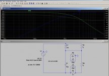
I did some thinking, I made some simulations and decided to use this "system" as a Continiously Variable Midrange Level Selector in my ongoing project.
It's symply a BSC with adjustable depth and I can't think of a proper name for it.
The maximum depth is adjustable by the R in paralel with the L (primary winding) of the BSC.
Now the transformes are ordered (laminated E-type Iron cores) and I will report when I have some practical results.
I have topic in Bulgarian language in my forum: ????????? BSC ??? Continious Correction Midrange
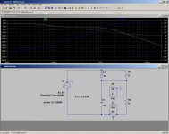
I apply two screenshots of two simulations, one with 128 ohms of loading load and one with 0.1 ohms loading load.
Additionally a selector for different additional capacitors can be added in order to maintain one an the same either acoustical or electrical crossover frequency.
Best regards!
P.S. Only a slight correction for the above statements. Core saturation is not the case here. Only ordinary transformer qualities. Bigger current draw=less impedance for the primary. So far no negative side effects predicted. I will have the system electrically measured for added distortion and what so ever once it is ready. - hope that is soon!
It's symply a BSC with adjustable depth and I can't think of a proper name for it.
The maximum depth is adjustable by the R in paralel with the L (primary winding) of the BSC.
Now the transformes are ordered (laminated E-type Iron cores) and I will report when I have some practical results.
I have topic in Bulgarian language in my forum: ????????? BSC ??? Continious Correction Midrange
I apply two screenshots of two simulations, one with 128 ohms of loading load and one with 0.1 ohms loading load.
Additionally a selector for different additional capacitors can be added in order to maintain one an the same either acoustical or electrical crossover frequency.
Best regards!
P.S. Only a slight correction for the above statements. Core saturation is not the case here. Only ordinary transformer qualities. Bigger current draw=less impedance for the primary. So far no negative side effects predicted. I will have the system electrically measured for added distortion and what so ever once it is ready. - hope that is soon!
Attachments
Last edited:
It definitely has lots to do with core saturation.
I don't think saturation or current draw has anything to do with it. Drawing more current through a transformer by increasing the load does not effect the flux density, it only effects the losses. If one has a particularly lossy transformer, then increased current draw could have a noticeable effect as frequency increases but I suspect this is not the main mechanism at work in the concept.
dave
Dave, look at the "p.s." part of my last post, I have made the same notice.
Meanwhile I found out yet another thing.
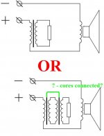
If we have a normal inductance and a transformer with primary and secondary winding with equal properties to the normal inductance and do the following:
a. Connect the single inductance in parallel with a 4 ohm resistor, and
b. Connect the primary winding of the transformer in parallel with a 8 ohm resistor and the secondary winding again with a 8 ohm resistor;
Then we get exactly the same curves.
Only one difference though the single resistor carries more load than the two resistors together.
The two resistors both carry signal at maximum of -9 db, which is about -4.5 db roughly and the single resistor is at -3 db peak level.
So the transformer and two resistors version will dissipate less heat through resistors and more through the transformer core.
At a ratio of 0.65:1 for the loading resistor of the secondary winding versus a single resistor in a BSC this means less demand for power capacity of the loading element as part of the job is done by the transformer core.
And this is only for transformers with efficiency of 99-100% which do not exist.
Probably the loading element will have to be no more than 0.5 times the power capacity of the R in a RL.
The price of the transformer itself may be too big to justify the savings from smaller resistor.
It may seem that the loading resistor is not in the signal path, but it actually is exactly there.
With those transformers I ordered I may end with just a 3.25, 7.5 and 15 mh low DCR iron cored inductances... which is not that bad...
WAIT!
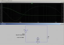
Circuits are not equivalent! I was mislead by sims with my intended crossover!
They are different (see attached screenshots) and it is now obvious that someone who is qualified enough must speak. - Because obviously I am not such person.
I almost mislead myself.
And in the transformer version the loading resistor and the bypass one do not get equal loading. They are equal to one point after which the loading one gets less current and the bypass gets more.
More thinking needed!
Meanwhile I found out yet another thing.
If we have a normal inductance and a transformer with primary and secondary winding with equal properties to the normal inductance and do the following:
a. Connect the single inductance in parallel with a 4 ohm resistor, and
b. Connect the primary winding of the transformer in parallel with a 8 ohm resistor and the secondary winding again with a 8 ohm resistor;
Then we get exactly the same curves.
Only one difference though the single resistor carries more load than the two resistors together.
The two resistors both carry signal at maximum of -9 db, which is about -4.5 db roughly and the single resistor is at -3 db peak level.
So the transformer and two resistors version will dissipate less heat through resistors and more through the transformer core.
At a ratio of 0.65:1 for the loading resistor of the secondary winding versus a single resistor in a BSC this means less demand for power capacity of the loading element as part of the job is done by the transformer core.
And this is only for transformers with efficiency of 99-100% which do not exist.
Probably the loading element will have to be no more than 0.5 times the power capacity of the R in a RL.
The price of the transformer itself may be too big to justify the savings from smaller resistor.
It may seem that the loading resistor is not in the signal path, but it actually is exactly there.
With those transformers I ordered I may end with just a 3.25, 7.5 and 15 mh low DCR iron cored inductances... which is not that bad...
WAIT!
Circuits are not equivalent! I was mislead by sims with my intended crossover!
They are different (see attached screenshots) and it is now obvious that someone who is qualified enough must speak. - Because obviously I am not such person.
I almost mislead myself.
And in the transformer version the loading resistor and the bypass one do not get equal loading. They are equal to one point after which the loading one gets less current and the bypass gets more.
More thinking needed!
Attachments
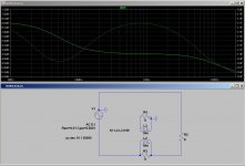
With different values of the primary and secondary windings it gets even more interesting. You can adjust the slope, depth of the first level region and the depth of the second step down.
Different bypass and loading resistor values lead to many opportunities along with the possibility to avoid the bypass resistor.
Too much examples and we (at least I) still don't have the general rule or principle. That makes posting more examples useless until someone gives some kind of theory.
Only thing that i found out is that with many attempts the output of this thing can be quite tailored.
I'll do some real experiments on second and third order crossovers in the loading of the secondary winding. - This will be done if a common ground can be used in order to accommodate the elements in parallel.
Best regards to all!
Transformers are just complex bandpass filters. If you make the coupling factor in your sim 1 rather than .99 you will see the second corner disappear. In simplest terms for an ideal model, the K of .99 simply puts a small percent of the total inductance in series with the primary which represents leakage inductance.
your version of the transformer can also be modeled with two series inductors and give you the same result. Of course the non-ideal nature of transformers could be used to your advantage but that really opens up a hit or miss situation unless you are able to know and spec the exact transformer you need.
It seems if someone wanted to follow this approach it would be best attacked with simulations and known easily measurable parameters which the series non-coupled inductors provide. As an extra plus, you could tap the inductors to allow for ease of tuning.
dave
You are right Dave. I tried that and the smaller is the coupling the bigger is the second step no matter of the loading.
For instance under 0.9 the loading resistor only alters the slope of the first step, but almost does not alter the depth of the correction.
Anyway, thanks for the input. But I have to say that i don't feel that I am the right person to investigate this kind of circuits and to share an all situations valid conclusions.
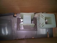
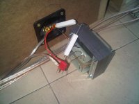
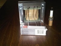
Never the less I progress Today I got two sets of laminated E-transformer cores with 36x36 mm central cross sections. The cores are handled to the engineers who will make the transformers and will measure their characteristics, which i will share.
The finished correction circuits will be incorporated in the project in my signature (where I could use and will appreciate any help on the bass enclosure ) and I will share further data and listening impressions.
Here-below I apply a photo of the material for the cores -and choke coil.
Best Regards to all!
EDIT (forgot to ask) What coupling coefficient should be expected from this type of transformer and core? The segments are laminated (I read that in the Wikipedia, that the segments should be electrically separate in order to keep the losses and etc. low)
For instance under 0.9 the loading resistor only alters the slope of the first step, but almost does not alter the depth of the correction.
Anyway, thanks for the input. But I have to say that i don't feel that I am the right person to investigate this kind of circuits and to share an all situations valid conclusions.
Never the less I progress
Today I got two sets of laminated E-transformer cores with 36x36 mm central cross sections. The cores are handled to the engineers who will make the transformers and will measure their characteristics, which i will share.The finished correction circuits will be incorporated in the project in my signature (where I could use and will appreciate any help on the bass enclosure
) and I will share further data and listening impressions.Here-below I apply a photo of the material for the cores -and choke coil.
Best Regards to all!
EDIT (forgot to ask) What coupling coefficient should be expected from this type of transformer and core? The segments are laminated (I read that in the Wikipedia, that the segments should be electrically separate in order to keep the losses and etc. low)
Attachments
Last edited:
I used this type of approach with an air core transformer which I created by winding a 20awg secondary with about a 4:1 turns ratio on a large 12awg inductor form with about a 12mH primary winding. This allowed me to do some relatively narrowband attenuation EQ of the Iron Lawbreakers in the mutual coupling region of the air core transformer which was centered at about 150hz with only an additional resistor and film capacitor.
This worked out very well since the air core transformer doubled as a low pass series inductor above the mutual coupling range and allowed optimization of the frequency response at the same time greatly flattening the impedance throughout the bass to lower midband range with minimum parts count and low signal loss. In fact, this approach, in addition to special internal speaker damping I used that included adsorbents virtually eliminated the upper BR impedance peak (18 ohms +/- 20% from 40 hz ~ 250hz without any 'Zobel' networks) which I believe results in significantly clearer sounding bass. The 'downside' was that the whole development process was very empirical - there were few if any 'guidelines' to work from for using an air core transformer as part of a speaker xover.
This worked out very well since the air core transformer doubled as a low pass series inductor above the mutual coupling range and allowed optimization of the frequency response at the same time greatly flattening the impedance throughout the bass to lower midband range with minimum parts count and low signal loss. In fact, this approach, in addition to special internal speaker damping I used that included adsorbents virtually eliminated the upper BR impedance peak (18 ohms +/- 20% from 40 hz ~ 250hz without any 'Zobel' networks) which I believe results in significantly clearer sounding bass. The 'downside' was that the whole development process was very empirical - there were few if any 'guidelines' to work from for using an air core transformer as part of a speaker xover.
Last edited:
Transformers ready!
Primary winding 120 turns of 1.2 mm wire;
Secondary winding 120 turns of 0.8 mm wire;
Resistance of primary - 0.33 ohms;
Resistance of secondary - 0.79 ohms;
Inductance of both windings in final variant with 1.5 mm spacer - 10 mh;
Inductance with fully closed core (E+I) 31.7 mh;
Inductance with only E core - 4 mh;
inductance with full core (E+I), but with 1.5 mm separator between the top and bottom sets of E+I lamellas - 10 mh;
4.7 to 10 Kohms load on the secondary leads to maximal primary inductance of ~10 mh;
Short circuit of the secondary leads to almost none inductance of the primary;
Experiments with secondary winding with 30 turns have been carried out and dully documented as follows:
Secondary on short circuit leads to primary inductance of 0.235 mh;
Secondary loaded with 10 ohms leads to 8 mh of primary;
Secondary loaded with 27 ohms leads to 8.92 mh of primary;
Secondary loaded with 37 ohms leads to 9.33 mh of primary.
I am very happy with the results!
************************************************
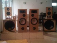
Because I am curious and my friend who made speakers with the same bass drivers as those from the project from my signature was curious too, we tried connecting the 10 mh as a simple BSC with 6.6 ohms bypass resistance and optionally with 1 mf capacitor. - We are very pleased with the results. We got ~29 hz at 0 db this way the bass became better articulated and detailed too.
************************************************
Experiments with variable loading of the secondary winding in my project are coming (maybe on Easter...) as well as listening impressions...
I apply some photos.
p.s. By the way, i have never heard a BSC before... - good thing is this!
Primary winding 120 turns of 1.2 mm wire;
Secondary winding 120 turns of 0.8 mm wire;
Resistance of primary - 0.33 ohms;
Resistance of secondary - 0.79 ohms;
Inductance of both windings in final variant with 1.5 mm spacer - 10 mh;
Inductance with fully closed core (E+I) 31.7 mh;
Inductance with only E core - 4 mh;
inductance with full core (E+I), but with 1.5 mm separator between the top and bottom sets of E+I lamellas - 10 mh;
4.7 to 10 Kohms load on the secondary leads to maximal primary inductance of ~10 mh;
Short circuit of the secondary leads to almost none inductance of the primary;
Experiments with secondary winding with 30 turns have been carried out and dully documented as follows:
Secondary on short circuit leads to primary inductance of 0.235 mh;
Secondary loaded with 10 ohms leads to 8 mh of primary;
Secondary loaded with 27 ohms leads to 8.92 mh of primary;
Secondary loaded with 37 ohms leads to 9.33 mh of primary.
I am very happy with the results!
************************************************
Because I am curious and my friend who made speakers with the same bass drivers as those from the project from my signature was curious too, we tried connecting the 10 mh as a simple BSC with 6.6 ohms bypass resistance and optionally with 1 mf capacitor. - We are very pleased with the results. We got ~29 hz at 0 db this way
the bass became better articulated and detailed too.************************************************
Experiments with variable loading of the secondary winding in my project are coming (maybe on Easter...) as well as listening impressions...
I apply some photos.
p.s. By the way, i have never heard a BSC before...
- good thing is this! Attachments
From series I went to parallel, because I found out that with the software used for simulations, serial circuits are not being simulated correctly. - the flat zone of the full range below crossover frequency should not be there.
Another interesting fact is that 90 degrees of phase difference at 1250 hz i quite a challenge for alignment. Both drivers in phase lead to ~ 20 to 32 cm (8 to over 12 in) required acoustical center offset. And full range out of phase leads to about 6 cm required offset. Curious fact is that on this frequency the delays are very easily detectable and noticeable.
Also I moved the constant inductance from before the variable BSC transformer to downstream from it.
It seems that with varying the loading of the secondary winding and thus shaping the electrical signal energy distribution, it is required to alter the value of the capacitor for the high pass for the full range. This is due to a probable actual crossover point shift.
Very funny such a simple circuit with so few parts to present such complicated challenges. Another challenge is the flat area in the electrical response of the variable BSC, with small value load all is normal and the signal falls with 6 db/oct after say 1000-1200 hz, but with 8 or 15 or greater load there is a flat plane where before was a slope.
Probably I will have to consult an engineer again for those issues as I am very optimistic about the results from a well engineered network with that device implemented in it. The listening tests were quite promising with only one flaw apart from the required acoustical centers offset - discrimination of complicated signals around crossover frequency - sound from falling thin metal objects is greatly jammed - this is ringing, tangling, jingling and etc. - great example is the Dire Straits song "Private Investigations" - there is such passage in it...
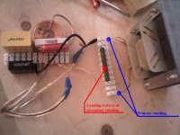
I apply a photo of the test crossover auditioned. Later it received a powerful potentiometer (two out of three leads of an adjustable L-pad used) and it made even more obvious the difference between settings.
Note that in the photo you'll see a zobel network not shown on the simulated circuits above, because the software is not able to simulate an R (driver) bypassed by a zobel. The zobel is 10 ohm and 8.2 uf and is for the bass driver.
Best regards to all!
Another interesting fact is that 90 degrees of phase difference at 1250 hz i quite a challenge for alignment. Both drivers in phase lead to ~ 20 to 32 cm (8 to over 12 in) required acoustical center offset. And full range out of phase leads to about 6 cm required offset. Curious fact is that on this frequency the delays are very easily detectable and noticeable.
Also I moved the constant inductance from before the variable BSC transformer to downstream from it.
It seems that with varying the loading of the secondary winding and thus shaping the electrical signal energy distribution, it is required to alter the value of the capacitor for the high pass for the full range. This is due to a probable actual crossover point shift.
Very funny such a simple circuit with so few parts to present such complicated challenges. Another challenge is the flat area in the electrical response of the variable BSC, with small value load all is normal and the signal falls with 6 db/oct after say 1000-1200 hz, but with 8 or 15 or greater load there is a flat plane where before was a slope.
Probably I will have to consult an engineer again for those issues as I am very optimistic about the results from a well engineered network with that device implemented in it. The listening tests were quite promising with only one flaw apart from the required acoustical centers offset - discrimination of complicated signals around crossover frequency - sound from falling thin metal objects is greatly jammed - this is ringing, tangling, jingling and etc. - great example is the Dire Straits song "Private Investigations" - there is such passage in it...
I apply a photo of the test crossover auditioned. Later it received a powerful potentiometer (two out of three leads of an adjustable L-pad used) and it made even more obvious the difference between settings.
Note that in the photo you'll see a zobel network not shown on the simulated circuits above, because the software is not able to simulate an R (driver) bypassed by a zobel. The zobel is 10 ohm and 8.2 uf and is for the bass driver.
Best regards to all!
Attachments
Last edited:
- Status
- This old topic is closed. If you want to reopen this topic, contact a moderator using the "Report Post" button.
- Home
- Loudspeakers
- Full Range
- L here, L there, L Everywhere *-*