Hi all
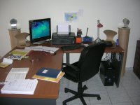
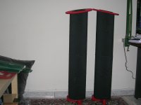
This is a “custom design” speaker “enclosure” for my 18 y.o. daughter.
It is a means to convince her that it is worthy having a more descent sound in her student apartment than the one she has now (she is happy to use the ASUS PG191 PC monitor speakers+Sub as the sole reproducer of sound for listening to .mp3 music files, web radio, video DVDs and TV through the soundcard).
She lives in a city away from where I’m living, so I had to build the speakers in her own apartment.
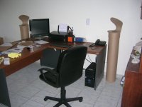
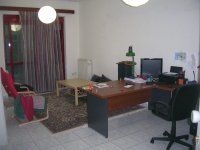
Therefore, ease of implementation and maintaining a clean “construction site” was a pivotal factor for to gain her permission to build it. In addition to this, the speaker had to be floorstanding with small footprint, lightweight and “aesthetically acceptable”. My contribution to the specification list was that it had to be built with pocket money and in a way that it would accept a better motor some months latter without major modifications.
Finally, it had to be constructed as a disposable - or at least as a recyclable - item in case that she wouldn’t like it.
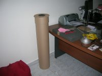
Packaging paper (roll carton) is the material to fulfill all the above requirements, plus some.
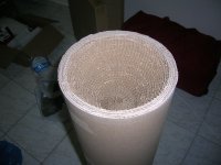
The carton allows for a multicell guide that minimizes internal reflections along with some mild HF attenuation down the cylinder axis, resulting in very clear midfrequency reproduction even with the currently installed crappy motor.
(a cheap 5 Euro coaxial 3.25 inches car speaker with an fc ~200Hz).
Not much of bass frequencies, but quite a balanced –bandwidth restricted-sound. The target of clear mids is achieved.
Any suggestions for 100-150Euro/pair, 4-6 inches full range motor is welcome.
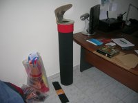
The speaker lends itself to artistic trimming by drawing or painting directly over it’s outer surface. It can also be easily dressed-up and undressed with color paper or fabric.
This is a “custom design” speaker “enclosure” for my 18 y.o. daughter.
It is a means to convince her that it is worthy having a more descent sound in her student apartment than the one she has now (she is happy to use the ASUS PG191 PC monitor speakers+Sub as the sole reproducer of sound for listening to .mp3 music files, web radio, video DVDs and TV through the soundcard).
She lives in a city away from where I’m living, so I had to build the speakers in her own apartment.
Therefore, ease of implementation and maintaining a clean “construction site” was a pivotal factor for to gain her permission to build it. In addition to this, the speaker had to be floorstanding with small footprint, lightweight and “aesthetically acceptable”. My contribution to the specification list was that it had to be built with pocket money and in a way that it would accept a better motor some months latter without major modifications.
Finally, it had to be constructed as a disposable - or at least as a recyclable - item in case that she wouldn’t like it.
Packaging paper (roll carton) is the material to fulfill all the above requirements, plus some.
The carton allows for a multicell guide that minimizes internal reflections along with some mild HF attenuation down the cylinder axis, resulting in very clear midfrequency reproduction even with the currently installed crappy motor.
(a cheap 5 Euro coaxial 3.25 inches car speaker with an fc ~200Hz).
Not much of bass frequencies, but quite a balanced –bandwidth restricted-sound. The target of clear mids is achieved.
Any suggestions for 100-150Euro/pair, 4-6 inches full range motor is welcome.
The speaker lends itself to artistic trimming by drawing or painting directly over it’s outer surface. It can also be easily dressed-up and undressed with color paper or fabric.
Attachments
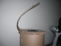
The addition of a reflector provides a degree to directional control over the speaker’s output, increasing the dialogue intelligibility when watching TV from the far side of the -now naked and acoustically live- room.
For listening to classic music I prefer not to use this reflector, but for modern pop music it’s use is acceptable.
Reducing reflector’s size and/or adding some hard and more reflective surface (kitchen aluminum foil laid over part of reflector’s surface) is something that I can try these days.
For listening to classic music I prefer not to use this reflector, but for modern pop music it’s use is acceptable.
Reducing reflector’s size and/or adding some hard and more reflective surface (kitchen aluminum foil laid over part of reflector’s surface) is something that I can try these days.
Attachments
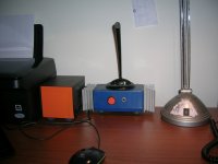
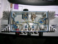
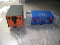
The speakers are driven by an LM3886 chip amplifier that I built 6 years ago
(I am still trying to persuade my daughter to accept having two more boxes on her desk. The shape and colour of the PSU/Amp combo may influence her decision).
Regards
George
(I am still trying to persuade my daughter to accept having two more boxes on her desk. The shape and colour of the PSU/Amp combo may influence her decision).
Regards
George
Attachments
Last edited:
Now this is the true DIY SPIRIT! Cant let good people go through life with crappy computer speakers now can we? Cheers to you sir, looks like a very interesting design. Seems like this would be great for a medium Q full-range driver with a nice off-axis response? Some of those Vifa or Tang-band drivers maybe....
mctavish
Thank you for your kind words.
Yes, crapy PC speakers make me nervous. But young people are used to them.
Anyway. This construction is easy to implement.
It will take ~2 months till I go home where I could build it again and take some measurements.
I would be glad if you or anyone else build such a construction using a motor you are familiar with it's sound and report back.
Regards
george
Approximately how would the dimensions be with this 3" driver? (If it's suitable at all!)
BB 3.01 - Omnes Audio 3 inch full range driver - Europe Audio
BB 3.01 - Omnes Audio 3 inch full range driver - Europe Audio
Dear kristleifur
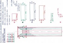
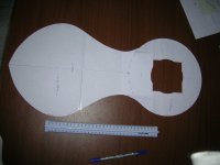
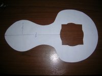
For fc=95Hz of this motor you link to, the tube hight should be 0.9m (1/4 wavelength)*. You can use the drawing I used and subtract 10cm from the hight of each roll.
I would not reduce the diameter of the tube.
It takes about 30m of roll carton to build two "enclosures". Here it costs 0.4Euro/meter=12 Euro total.
But you can start by building just one enclosure (6 euros), listen to it and then decide if it worts spending another 6 euros.
Regards
George
*PS rovided it works as a MLQW. I am not sure if this is so. An impedance plot should clear this out.
For fc=95Hz of this motor you link to, the tube hight should be 0.9m (1/4 wavelength)*. You can use the drawing I used and subtract 10cm from the hight of each roll.
I would not reduce the diameter of the tube.
It takes about 30m of roll carton to build two "enclosures". Here it costs 0.4Euro/meter=12 Euro total.
But you can start by building just one enclosure (6 euros), listen to it and then decide if it worts spending another 6 euros.
Regards
George
*PS
rovided it works as a MLQW. I am not sure if this is so. An impedance plot should clear this out.
Last edited:
Norman
I am located far away from Japan, but these speakers
http://www.diyaudio.com/forums/full-range/65061-full-range-speaker-photo-gallery-18.html#post816921
still sound good to my ears.
(It takes some OB to match (?) them.
Regards
George
I am located far away from Japan, but these speakers
http://www.diyaudio.com/forums/full-range/65061-full-range-speaker-photo-gallery-18.html#post816921
still sound good to my ears.
(It takes some OB to match (?) them.
Regards
George
Last edited:
Edit time for post #9 expired , so I will post the intended edit here:
PS2: Due to the fact that untreated roll carton is quite lossy, impedance plot might show an aperiodic loading. If this is the case, the exact hight of the cylinder is not important at all.
Regards
George
PS2: Due to the fact that untreated roll carton is quite lossy, impedance plot might show an aperiodic loading. If this is the case, the exact hight of the cylinder is not important at all.
Regards
George
Thank you Norman.
Hi all
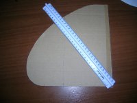
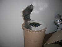
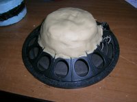
I made a smaller reflector for the tuby enclosure. This reflector, as the larger one (the circular speaker baffle as well) is made of two roll carton pieces glued together using silicon bathroom sealant. It takes 1/2 hour for the sealant to set, but it's acid smell takes 2 days to go away out in the open.
Hi all
I made a smaller reflector for the tuby enclosure. This reflector, as the larger one (the circular speaker baffle as well) is made of two roll carton pieces glued together using silicon bathroom sealant. It takes 1/2 hour for the sealant to set, but it's acid smell takes 2 days to go away out in the open.
Attachments
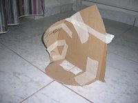
The sound using the small reflector is perceived as more detailed compared to the sound with no reflector and more open and detailed compared to the sound with the large reflector.
Next, I covered (glued with office paper glue) the small reflector with kitchen aluminum foil. Contrary to what I was afraid of, the sound did not become edgy and aggressive, but one more step higher in details.
This is a good progress up to here.
Thanks for reading.
Regards
George
Next, I covered (glued with office paper glue) the small reflector with kitchen aluminum foil. Contrary to what I was afraid of, the sound did not become edgy and aggressive, but one more step higher in details.
This is a good progress up to here.
Thanks for reading.
Regards
George
Attachments
Hi all
I have done a few changes to the speakers.
First two 6.5 inches drivers were installed. They were removed some 10 years ago from an old Ford Granada.
Some mods (whizzers removed, paper cone treated with shellac -5 passes- and plumper’s putty around the magnet) made it sound better to my ears.
Then paper roll Tube bottom raised 5cm above the floor through stands, making for an open-end pipe.
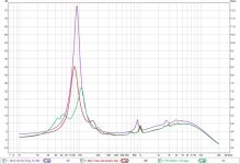
Impedance Plots:
Pink: Speaker on air.
Red: Speaker on closed-end pipe.
Green: Speaker on open-end pipe.
I have done a few changes to the speakers.
First two 6.5 inches drivers were installed. They were removed some 10 years ago from an old Ford Granada.
Some mods (whizzers removed, paper cone treated with shellac -5 passes- and plumper’s putty around the magnet) made it sound better to my ears.
Then paper roll Tube bottom raised 5cm above the floor through stands, making for an open-end pipe.
Impedance Plots:
Pink: Speaker on air.
Red: Speaker on closed-end pipe.
Green: Speaker on open-end pipe.
Attachments

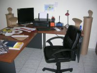
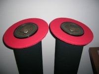
Next, the tube top was cut ~20 degrees from horizontal. Turning each speaker around it’s vertical axis, allows for directivity and off the wall reflections control, without using reflectors on top of the speakers.
Two larger 29cm dia circular wooden baffles and wooden phase plugs were prepared and tested, but rejected by the user (“too serious looking” and “these silly projecting things” were the comments for the baffles and the plugs respectively).
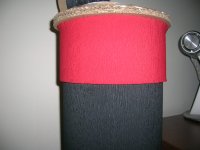
Therefore phase plugs removed and wooden baffles replaced with paper baffles dressed in red.
Two larger 29cm dia circular wooden baffles and wooden phase plugs were prepared and tested, but rejected by the user (“too serious looking” and “these silly projecting things” were the comments for the baffles and the plugs respectively).
Therefore phase plugs removed and wooden baffles replaced with paper baffles dressed in red.
Attachments
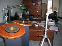
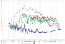
Positioning the two speakers close together instead of having them separated by a distance as is normal for stereo, gives a better over all performance at least for this room and listening positions.
Freq Response:
(Pink): Tube Out.
Mic on Carpet 0.03m below Column Output
(Red): Close-Up Both Speakers.
Mic 0.3m from Speakers Center, Baffle Level , Horiz Position
(Green): Far Both Speakers.
Mic 1.2m from Speakers Center, Baffle Level , Horiz Position
(Blue): Ambient Noise. No Signal to Speakers.
Mic 1.2m from Speakers Center, Baffle Level , Horiz Position
Speakers driven through the External Ampl Headphone (L) Out.
Amp. Volume Control: Max (Fully CW)
Piezo Mic through Mic Pre to Soundcard (C-Media PCI Audio Device)Line In
Room Eq5 Settings (Log Sweep):
Sample Rate: 44.1k
Word Length 256k
Sweeps:2
Actually the merit of this “one spot” speaker placement is something that I am after some time now.
I don’t know how to test the validity of such a hypothesis-or luck of it- by acoustic measurement. I am open to suggestions.
Regards
George
<edit> First plot is with 1/48 Octave smoothing.
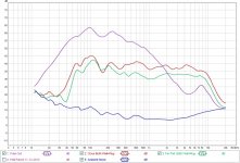
Second plot (1/3 Octave smoothing), for just to make trends easier to see
Freq Response:
(Pink): Tube Out.
Mic on Carpet 0.03m below Column Output
(Red): Close-Up Both Speakers.
Mic 0.3m from Speakers Center, Baffle Level , Horiz Position
(Green): Far Both Speakers.
Mic 1.2m from Speakers Center, Baffle Level , Horiz Position
(Blue): Ambient Noise. No Signal to Speakers.
Mic 1.2m from Speakers Center, Baffle Level , Horiz Position
Speakers driven through the External Ampl Headphone (L) Out.
Amp. Volume Control: Max (Fully CW)
Piezo Mic through Mic Pre to Soundcard (C-Media PCI Audio Device)Line In
Room Eq5 Settings (Log Sweep):
Sample Rate: 44.1k
Word Length 256k
Sweeps:2
Actually the merit of this “one spot” speaker placement is something that I am after some time now.
I don’t know how to test the validity of such a hypothesis-or luck of it- by acoustic measurement. I am open to suggestions.
Regards
George
<edit> First plot is with 1/48 Octave smoothing.
Second plot (1/3 Octave smoothing), for just to make trends easier to see
Attachments
Last edited:
- Status
- This old topic is closed. If you want to reopen this topic, contact a moderator using the "Report Post" button.
- Home
- Loudspeakers
- Full Range
- Cheap & easy cylindrical column loudspeaker