GM, that's a Karlson modeled in HornResp??
Or?
Yes and no, as I noted, it's a 4th order band-pass alignment (BP = type 1 in LspCad), i.e. it encompasses only the basic front and rear coupling chambers of a K-15 or a basic Klam alignment that I use as a guideline to decide if the driver's specs are suitable for a K-15 and/or Klam loading concept.
GM
Karlson is probably a distributed circuit problem, not
easily broken down to manageable number of lumped elements.
OK, it's my understanding that AkAbak can model all but the odd shaped vent as a series of expanding/contracting shaped ducts; so if you're right, a K-15 can be ~accurately simmed except with a vent of the same area/thickness, so load a known driver's specs that Freddy has a measured response of to see how close it is. If the sim is fundamentally different between its two half space (2pi) F6 points, then the slot is affecting the front chamber's loading more than I'm currently giving it credit for.
GM
here's my long-distance friend's work so far on a little test coupler for FE206E (front mount) and W8-1772 (rear mount) - its about the size of that old coupler that starts this thread - there's a partial shelf which will allow building up a front deflection shelf and a rear lowpass choke
Karlson-expert Carl Neuser suggested examining the following apertures besides radial arc and there's quite a difference in overall aperture area 83.6 square inches vs 131.9 square inches.
Gap Slope p q Area Length Wmax
0.25 1.5 3 12 83.6 18.5 12
x w
0.00 0.50
1.00 0.50
2.00 0.52
3.00 0.55
4.00 0.62
5.00 0.74
6.00 0.92
7.00 1.16
8.00 1.49
9.00 1.91
10.00 2.43
11.00 3.07
12.00 3.84
13.00 4.74
14.00 5.78
15.00 6.97
16.00 8.29
17.00 9.73
18.00 11.24
18.50 12.00
********************
Number Two
Gap Slope p q Area Length Wmax
0.5 2.9 1.08 9.5 131.9 18.5 12
Aperture
x w
0 0.50
1 0.78
2 1.10
3 1.43
4 1.76
5 2.11
6 2.46
7 2.81
8 3.17
9 3.54
10 3.91
11 4.30
12 4.72
13 5.18
14 5.73
15 6.43
16 7.38
17 8.72
18 10.69
18.5 12.00
****************
two vents will be examined - one being the horizontal slot vent which hopefully is tuned high enough to allow tuning lower, then that vent will be plugged and the driver gapped from the baffle to form the other vent under investigation.
An externally hosted image should be here but it was not working when we last tested it.
An externally hosted image should be here but it was not working when we last tested it.
Karlson-expert Carl Neuser suggested examining the following apertures besides radial arc and there's quite a difference in overall aperture area 83.6 square inches vs 131.9 square inches.
Gap Slope p q Area Length Wmax
0.25 1.5 3 12 83.6 18.5 12
x w
0.00 0.50
1.00 0.50
2.00 0.52
3.00 0.55
4.00 0.62
5.00 0.74
6.00 0.92
7.00 1.16
8.00 1.49
9.00 1.91
10.00 2.43
11.00 3.07
12.00 3.84
13.00 4.74
14.00 5.78
15.00 6.97
16.00 8.29
17.00 9.73
18.00 11.24
18.50 12.00
********************
Number Two
Gap Slope p q Area Length Wmax
0.5 2.9 1.08 9.5 131.9 18.5 12
Aperture
x w
0 0.50
1 0.78
2 1.10
3 1.43
4 1.76
5 2.11
6 2.46
7 2.81
8 3.17
9 3.54
10 3.91
11 4.30
12 4.72
13 5.18
14 5.73
15 6.43
16 7.38
17 8.72
18 10.69
18.5 12.00
****************
two vents will be examined - one being the horizontal slot vent which hopefully is tuned high enough to allow tuning lower, then that vent will be plugged and the driver gapped from the baffle to form the other vent under investigation.
Last edited:
May be going the wrong way, making short circuit path even shorter.
Driver gapped on baffle would be the worst possible case.
Hopefully your experiment should give the evidence. One solution may
be a rear shelf that extends fully to brace the back, gaps relocated
toward the sides instead. Same Hemholtz tuning per each chamber I
would hope, but leakaround for lowest frequencies takes longer detour.
Last edited:
that possibility certainly exists - that vent position seems to work/sound alright in JEK's "Karlsonette" (1st commercial Karlson 12 enclosure of fall 1954) fwiw Carl likes the basket gapped from the baffle vent method sound. One thing I would think would be helpful on making new couplers would be a cheap test-mule with radial arc wings, then a hinged baffle which would lock down at any needed angle with two wing nuts - that along with movable upper baffle might facilitate finding angles which avoid a large first dip using RTA sweeps or pink-noise while watching a monitor.
I'm not fully convinced to the value of Fig6 reflector versus its difficulty and time to make - it needs some builds and testing/comparisons. One 32" tall coupler I had made good graphs with a fully perpendicular board.
maybe its good to keep the K15 port position and arrangement alive while exploring smaller couplers - just leave off the front shelf for starters as too much front shelf may set up another chamber. Your rear lowpass shelf and side gaps should be examined and compared with music tracks.
Last edited:
Fig 6 is half baked. JEK had almost the right idea, but failed to realize
how Fig6 focus's to a horizontal stripe. Koupler exit slot is vertical...
Horizontal high order modes do collide and reinforce toward the center,
so the idea isn't completely wack, but you ain't getting away from dips
and peaks in the response if horizontal mode is between parallel walls.
Fig 666 (Crosley, cucoo clock, or dome shape?) address these concerns.
No parallel walls across the 2 widest modes, and focus to vertical stripe.
And then there is additional question of how Koupler should optimally
interact with front shelvage? And how the right front shelvage might
further detour the evil acoustic short circuit...
Last edited:
I have been toying with a modified / utterly misunderstood Karlson arrangement. Probably modified right out of that category, but what the heck.
Two Tang Band 8 inch woofers, Xmax of 12 mm, sensitivity of 84 db and full specs below in an attachment, mounted into a 90 degree chamber, tilted 45 degrees with a large Karlson slot to load them with. A fairly deep, 24 inch, open backed box, with an unknown and to be discovered amount of chopped cotton house wall batting hung at appropriate intervals. This follows John K's notion of a cardioid radiation pattern with the slight twist of another Karlson slot at the back. My initial reason for using these profiles was to provide a wider impedance load into the room, in an attempt to quell resonance nodes.
This lash up to be driven by class D amps and sharply rolled off above 100 Hz. A Berringer DCX 2496 with Jan Didden's board will be the crossover, so I will have a large playground in DSP to alter the FR and phase in.
The mid bass is an Eminence Delta 8, with a 200 watt power limit and 96 db efficiency, for 80 to 300 Hz and then a nude Lowther above this.
My question is simple, can anyone give me a thumb style notion, other than in my eye please, of where I will have to work on to get this to provide reasonable bass to 30Hz and max spl in the 103 db realm? Not asking for a detailed analysis, just off the cuff responses, going with a "first thought, best thought" attitude.
A pic below will give an idea of how far I have gotten. And any help, and negative comments, will be appreciated.
Bud
Attachments
Last edited:
Equidistant path up both sides of this front shelf.
Non-equidistant path up the middle is blocked.
Crude phase plug, but any improvement over the
regular shelf is still an improvement...
After that, its about getting echoes out the slot
in as few passes as possible. I'm playing to avoid
resonant modes that might favor one frequency
over another, or don't have quick n' obvious exit
strategy.
Attachments
I have been toying with a modified / utterly misunderstood Karlson arrangement. Probably modified right out of that category, but what the heck.
...
My question is simple, can anyone give me a thumb style notion, other than in my eye please, of where I will have to work on to get this to provide reasonable bass to 30Hz and max spl in the 103 db realm? Not asking for a detailed analysis, just off the cuff responses, going with a "first thought, best thought" attitude.
OK, if you really want to get that low with any authority using woofers with specs like that, IMO and IME your best bet is to put them in ML-TL type enclosures. Totally doable. Lose the Karlson bass scheme entirely. I don't see any benefit in this application.
For the upper bass / mids, I spose you might try a dipole Karlson type arrangement. See below. I originally thought of doing this as a variant of the H baffle dipole sub, in hopes of getting some 'free' excursion limitation. (to be verified...
") ) It would require a large driver to do this effectively, as do ordinary H baffles. But it may have some subjective benefits in you desired BW.
) It would require a large driver to do this effectively, as do ordinary H baffles. But it may have some subjective benefits in you desired BW. 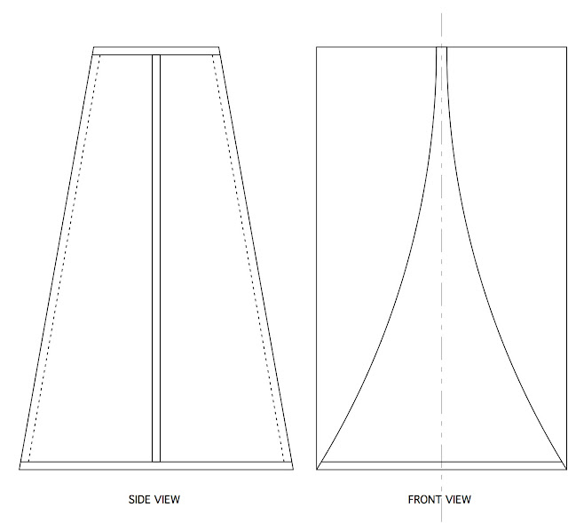
AFA the baffle less Lowther. I just don't get it.
What's the benefit supposed to be? It's ideal if you want to generate edge diffraction, but other than that I don't see what peoples' goals are with this approach. At least put it on a contoured elliptical baffle to eliminate some edges.
Last edited:
Regarding the original question of what does it take to reproduce drums, of course it depends. An early modestly sized DIY speaker I made did jazz level drums very realistically. I used them for recording monitors, and it was very difficult to tell they were not real drums. These used low distortion 8" woofer, a large focal midrange, and a horn tweeter in a TL with a very wide baffle (30" IIRC).
Now, rock drummers at full tilt are very loud, and the horn system GM pointed out might be about what it takes to achieve that.
The big Karlson K15s at least do a pretty good job at coming close to the slam of a real rock bass drum in a reasonable size. I have less experience at smaller sized karlsons, so I just have to say I don't know.
Before I cut out speaker hole, my 1955RE K15 cabinet was sitting right next
to a real kickdrum. Could pedal the padded hammer thingie (I'm no drummer,
don't know what its called). There was literally no difference... Especially if
the listener was in the next room. Pounding on blank baffle plate right about
where the speaker hole was fixin' to go. It sounds like a kick drum, cause it
IS a kick drum. Far as I can tell anyways... The slam was impossibly huge!
Somebody just fix a drumhead over that hole now... I wonder how hard it'd
be to remotely work that pedal from the around other side?
Last edited:
according to his posts, Dave Young made Cerwin-Vega B36 size couplers (3'x2'x2') for band subs back in the 80's for 18" but ended up loading with 15" as those went lower. I don't think they were "optimized" as he said there was a 20dB hole (would a front shelf offset that as with K15?). AT 100 watts and 40Hz, 3rd order distortion of a Peavey 15" went from over 100% in a FH1 (short path sealed rear chamber w-bin) to 8% (other 15s did better). I tried to draw the coupler from his description - some of them had a 6"x6" vent hole cut in the center of the upper board tuning to around 36Hz . If one could figure out before hand the angles to minimize the first dip, then things would be more fun. Perhaps it could be done in cheap plywood or particleboard taking notes and RTA(I don't believe CN would agree with DY's design order)
http://img232.imageshack.us/img232/9843/dy1815jpgah6.jpg
Dave's notes from Ulfman's forum
"As a low frequency cabinet, the Karlson is usable to 35hz with
low harmonic distortion. Like any enclosure that depends on porting to augment the bass output, Theile-Small parameters have
to be taken into consideration.
I have yet to measure anything of
comparitive size that came close. They get ugly above 175 hz. and require a crossover set from 100-150 hz.
The key to its low freq.performance is the coupled front chamber. The increased air pressure loads the cone and dampens it. A front loaded woofer and
a horn loaded woofer operating below cutoff doesn't have that advantage.
Twice I've measured the 3rd harmonic of 40hz(120 hz) louder than the fundamental with 100 watts feeding the speaker.
The Peavey FH-1 and a Yorkville 2-18 with RCF's. When the 1504-4
Black Widow was tested in a 12 cu. ft. Karlson, the 3rd harmonic
distortion went from 103% to 8%. I didn't have the Yorkville long
enough to switch speakers.
*************************************
In 1985 I redesigned the K18 as a 3'x2'x2' box with 2 casters on the lower back and 2 handles on the upper back.
A smaller enclosure had outperformed a Cerwin Vega B36 in terms of LF extention and harmonic distortion.
It was a good compromise for cutting 4'x8' sheets of plywood, transporting in vans and station wagons,
and stacking in a multiple cabinet PA system. Best results were obtained using 15" pro woofers.
Think about it. The low frequency cutoff is determined by the TS parameters and the port tuning.
An 18"EVM has a VAS of approx. 17 cu. ft. and a Fs of 34 Hz. A 15" EVM with a B cone has a VAS of 8 cu. ft.
and a Fs of 41 Hz. Put each in a 7 cu. ft. enclosure and see what happens. The 15 will produce more output at 42 hz
than the 18 because its fb is lower. according to some tests done on April 4, 1987 at 100 watts input,
the EVM 18 produced 117.5 db at 65 hz and 109 db at 40 hz. The EVM 15B :: 119.5 :: 65 hz & 115 :: 40 hz.
So the design approach is to do the rear chamber first, the overall size second, the taper third, and the front chamber fourth.
Use a driver with a Qts of .3-.35. JBL 140's and their like do produce a lower f3 but at the expense of reduced output below 80 hz.
That box had a 20 db hole at 250 hz,. sounded ugly if the crossover was higher than 150 hz, and had your typical for a Karlson rough frequency response above 300 hz.
I had better success for bass players using 2, X-15 cabinets stacked with the bottom enclosure inverted.
Good Luck
David A. Young
*******************************************************************************************
Details on Dave Young’s KLFE 1815
The 23" square baffle is inset 1" from the front and sits in a
20 degree angled slot cut by tilting a 3/4" wide dado blade on a table or radial arm saw. The sides have 1/4" deep routed slots to accept the baffle and top panel. The top panel is at 145 degrees
to the baffle and contains the port. The length is determined by
measuring the distance left over after the baffle is fitted and the top dado cut. The top slot is cut using a tilted dado blade.
The length will be between 11 and 12". Both the speaker hole and port are centered on their panels. I used a 6" ducted port on one pair and square holes on the rest. The coupler panels fit
into a 1/4" deep by 3/8" wide dado cut into the sides and top.
They are also braced to the baffle. The first batch had a
45 degree kick plate at the rear for casters and input jacks.
This way the back could be removed without having wires in the
way and it was possible to back the cabinet against a wall
without damaging the cables or connectors. The exterior is
36" high x 24" wide x 23 15/16" deep. The slot was calculated
from Poppe's formula with a modification by the guy who cut a
sheet metal template for me. I never tried a radial coupler on
the KLFE-1815. With the exponential opening, the slot is narrower
at the top. The gap at the top of the slot is 1/2".
Here are the Template dimentions.
0"-11 5/8" 12 3/8"-11" 24 3/8"-8 5/16"
1 3/8"-11 5/8" 13 3/8"-10 13/16" 25 3/8"-7 7/8"
2 3/8"-11 9/16" 14 3/8"-10 11/16" 26 3/8"-7 3/8"
3 3/8"-11 9/16" 15 3/8"-10 9/16" 27 3/8"-6 7/8"
4 3/8"-11 1/2" 16 3/8"-10 3/8" 28 3/8"-6 1/4"
5 3/8"-11 7/16" 17 3/8"-10 1/4" 29 3/8"-5 5/8"
6 3/8"-11 3/8" 18 3/8"-10" 30 3/8"-4 7/8"
7 3/8"-11 5/16" 19 3/8"-9 13/16" 31 3/8"-4 1/16"
8 3/8"-11 1/4" 20 3/8"-9 9/16" {32 3/8"-3" }
9 3/8"-11 3/16" 21 3/8"-9 5/16" {33 3/8"-2 1/8"}
10 3/8"-11 1/8" 22 3/8"-9" {34 3/8"-1" }
11 3/8"-11 1/16" 23 3/8"-8 11/16" {34 7/8"-3/8" }
{from here curve}
{was cut to fit}
Dave
**********************************************************
The Peavey 1504-4 produced 16.5% 2nd Harmonic Distortion at
40 hz,100 watts in the FH-1 and 5% in the Karlson Low Frequency
Enclosure 18"15" (KLFE-1815). With a 65 hz tone, the FH-1 was
5.5% 2nd and 16% 3rd. The KLFE-1815 produced 5.5% 2nd and
1.7% 3rd. The FH-1 is flat to 130 hz with a 12db/oct. rolloff.
The KLFE was at the same output level from 70-80 hz with 40 hz
being 8 db higher. Above 80 hz, the FH-1 was the winner. The
KLFE's first dip is at 230 hz.
I have never tried a 1505 in a Karlson.
--- --- --- --- --- --- --- --- ---
Replying to:
Dave -
do you have figures for the 100 watt 40Hz 2nd harmonic distortion of the Peavey 1504-4 in your K-1815? Also - do you have any other distortion data to present?
I was just wondering if the 120Hz (3rd harmonic of 40Hz) low distortion figure partly came from a power dip @ 120Hz in the K1815. Is your first K-1815 reposnse dip around 175Hz???
thanks, Freddy
**********************************
Last edited:
- Status
- This old topic is closed. If you want to reopen this topic, contact a moderator using the "Report Post" button.
- Home
- Loudspeakers
- Full Range
- how large does a Karlson need to be to get semblance of a bass drum?