I'm building a presence speaker to go with my Yamaha receiver, so experimenting with something cheap is in order.
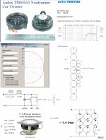
I already bought 16 of the Parts-Express.com:2" Full Range Aluminum Cone Neodymium Driver | 2" Full Range Aluminum Cone Neodymium Driver line array midbass woofer 2" driver shielded woofer midwoofer, and my idea is to put 8 of them in a horizontal line array that I'm making from a 3" PVC tube.
My question is about wiring, because while my receiver can handle a 4, or 6 ohm load, I don't think that it can do 4 ohms for separate channels and my other speakers are 8 ohms.
I want to wire them as close to 8 ohms as possible, and knowing very little about electronics, I wanted to ask if this would work.
The nominal resistance is 8 ohms, and the measured is 7.57.
If I wire 7 of them in series with 1 in parallel, the nominal resistance is 7 ohm, and the measured is 6.68.
I'm wondering if this will work, and will be OK for a receiver putting out 8 ohms.
Is there a better way to do this so I get 8 ohms?
The other option is to put 4 of them is series, against 4 of them in parallel, for 16 ohms, which will make them play less loudly, but here is the cool part. All of my speakers are Zaph b3s full ranges, with very low efficiency, so I could turn the volume down a little on them, and up on my array, and this might work, too. Could somebody who knows more about this give me some advice?
If I just wire all 8 in series for a 64 ohm load, and then parallel in an tweeter with a high pass cap, I'd get a ~7 ohm load, but would this be a poor wiring decision?
If you would have went with 9 drivers per side you could have had an even 8 ohm load with three paralleled groups of three drivers, all groups in series.
Here is a line array impedance "cheater chart".....
arrayimpedance
If you would have went with 9 drivers per side you could have had an even 8 ohm load with three paralleled groups of three drivers, all groups in series.
Here is a line array impedance "cheater chart".....
arrayimpedance
Thanks for your reply.
Unfortunately, I saw how good of an idea this was only a few hours after I bought these drivers.
However, after some searching around, I found the frequency response of these little drivers, and they pretty much drop off around 10k, so now I'm thinking I need to put a tweeter with them.
I live in Madison, WI, and I can just drive to Madisound and buy a 5$ tweeter and add a 1 uF cap for very cheap (and I don't really want to pay for shipping from PE for the extra 1 driver / side). So, I'm really leaning towards all 8 in series, with the tweeter in parallel.
I've never seen a schematic like the one that I'm proposing, so I'm worried that I'm going to do something horribly wrong and blow up my receiver/get no sound from the drivers. So, I guess I just want to know if this will work at all barring hi-fi sound.
I'm sure I'm asking stupid questions, but I basically have the parts and I'm sitting next to my computer waiting to get an answer to this question.
Would putting all the 2" in series to get a 64 ohm load, and putting that in parallel with a single 8 ohm tweeter have any negative effects besides the odd 7.1 ohm? It would sound like a 7.1 ohm speaker, not a 64 ohm one right?
Would putting all the 2" in series to get a 64 ohm load, and putting that in parallel with a single 8 ohm tweeter have any negative effects besides the odd 7.1 ohm? It would sound like a 7.1 ohm speaker, not a 64 ohm one right?
With the tweeters you have 9 drivers per side, connect 3 drivers in parallel, then the 3 groups in series.
Is it bad that the tweeter will be in series with the drivers? I've heard that this isn't desirable.
With the tweeters you have 9 drivers per side, connect 3 drivers in parallel, then the 3 groups in series.
Hi vinnie,
That’s a good idea. Here is a few more:
b
Attachments
Hi vinnie,
That’s a good idea. Here is a few more:
b
Wow, thanks for the awesome diagram!
Hmm, so it looks like if I tried to substitute a circuit for that 9th driver, I'd have to make a pretty large investment in parts to get equal LHR of the missing driver.
If it won't have too large of an impact on sound quality, I'll take Vinnie's advice.
Hi bunshi,
Vinni’s advice is the best for both the M and T drivers to adapt but I would also consider replacing the missing M driver with a simple 10-22 Ohm/5W wire-wound resistor and place physically the drivers that are in series with the mentioned resistor as driver # 1 and driver # 9 of the array.
I don’t think you would loose noticeable SQ doing this. Why cant you DIY-wind a simple 10 mH/ 4Ohm/ 5W coil by yourself, IMO an easy low cost challenge for a DIY'r?
b
I think I will try both, because I will be going back to Madisound, and they have an LRH meter (I don't have one), so I can test my diy coil. I can take measurements of both cases, and see how that affects the sound. BTW, why do I need to also substitute driver #1 and #9 and not just #9? I have 8 per side.
I think I will try both, because I will be going back to Madisound, and they have an LRH meter (I don't have one), so I can test my diy coil. I can take measurements of both cases, and see how that affects the sound. BTW, why do I need to also substitute driver #1 and #9 and not just #9? I have 8 per side.
See the picture and read my post hereabove again.

b
Attachments
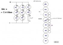
See the picture and read my post hereabove again.
b
Ok, yeah, it's clear. Thanks for the great advice btw.
- Status
- This old topic is closed. If you want to reopen this topic, contact a moderator using the "Report Post" button.
- Home
- Loudspeakers
- Full Range
- Line array wiring questions