Hi
I have been following the Frugal-Horn thread with much interest and am looking at building 5 Bruces for HT and HiFi (2 to start with to see how they sound) and was wondering if anyone has any comments on whether they are suitable to match with a subwoofer, either infinite baffle or Labhorn.
Has anyone tried this approach? The Bruce should play quite loud if it is only handling 80hz up and the crossover region should be quite smooth as the frequency response of the Bruce is quite flat at that frequency.
Would the Labhorn be overkill for these speakers? I guess at least I wouldn't need a powerful amp to drive it!!!
Is this a reasonable line of thinking or am I missing something?
cheers - DB
Hello,
I've a bit smaller type of Bruces this summer and I'm really pleased with them. After reading the Tapped Horn thread over and over again I decided to try to build one to my Bruces with the lower end.
The result is excellent. The tapped horn integrates nicely to Bruces. One thing that I'll might add is a feedback destroyer to get room modes eliminated.
I use old Yamaha amplifier for the sub, maybe 30W used...
So, I would recommend a tapped horn. Build a prototype and try it =)
--
Tuomas
tpakkanen and Scottmoose
Thanks for you comments as someone who has built something similar to what I have described!
Good to hear that your tapped horn worked well with the frugel horns... what crossover frequency and slope do you use? and are the mains highpassed or full range?
I'm not into insane volume levels (as Scottmoose said in another thread >85db = hearing damage), I just like plenty of headroom. I also like distortion free low bass extension. The room they are going into is a decent size too. Actually what I really like is for the sound to sound 'real'. That is what attracted me to the frugel horns - and their lack or crossover, and their good efficiency which should lead to low phase/compression/IM/harmonic distortion? I guess I'll know for sure once they are built...
Thanks Scottmoose for designing the frugel horns! Once I have completed mine I'll post the results back to the main thread.
cheers, DB")
Thanks for you comments as someone who has built something similar to what I have described!
Good to hear that your tapped horn worked well with the frugel horns... what crossover frequency and slope do you use? and are the mains highpassed or full range?
I'm not into insane volume levels (as Scottmoose said in another thread >85db = hearing damage), I just like plenty of headroom. I also like distortion free low bass extension. The room they are going into is a decent size too. Actually what I really like is for the sound to sound 'real'. That is what attracted me to the frugel horns - and their lack or crossover, and their good efficiency which should lead to low phase/compression/IM/harmonic distortion? I guess I'll know for sure once they are built...
Thanks Scottmoose for designing the frugel horns! Once I have completed mine I'll post the results back to the main thread.
cheers, DB
What were the frequency cutoffs of your tapped horns?
I would have thought the boxes would have to be quite large to go much under 40hz right?
I've got a 12" carbon fiber driver lying around that has an fs of 22hz and QTS of 0.29. I have been trying to figure out what to use it for and I think and a front loaded bass horn seems like a good option, being carbon fibre, cone should be light and strong, good for horn loading, has a big magnet too!
At 0.29 the QTS is probably too low for tapped horn isn't it?
I tried running it full range and it sounded ok up to 1khz or so but then it beams horribly and seems to have some breakup resonances or something.
cheers, DB
just a quick 'try it for fun'
I use an old RS1354 for tests. Wip up some styro panels with glue and test.
Which leads me to another type of Mfg. process. I studied the baffle shape and the front panel of the A166 (currently in SC). Without extensive, and costly, woodworking there was no way to get the suprabaffle/front panel to the desired shape that i saw as being efficent. I was looking for a more teardrop shape of the suprabaffle and a vertical radius, which blended into the suprabaffle, on the front baffle. This sim gave me the least edge diffraction and less direct reflections off the front panel.
Now , in the old days when we wanted a shape to test we would build a styro male mold and using as a release medium a cover of Saran wrap then overlay the mold with impregenated (rosin) fiberglass. This is the method used by Mr. Bede on his kit planes and the method i am using on my HY PO trike models for aerodynamic studies.
So to achieve the desired shapes on the A166 i will be using the above method. As i have acccess to a CMM the layers will be built up and ground down until the two horns match within a given tolerence.
Should be interesting. I just want to bring the A166 up to its total full potential.
ron
As an added note, i rejected the use of Carbon fiber in this application due to the cost and the need to vacumme form.
Greets!
DSL style tapped horns (as opposed to off-set driver pipe horns such as the BIB series) don't need nearly as much Vb as these or other style horns due to using both sides of the driver to load it. It still needs a 1/4 WL long path-length of the desired Fc (Fp) though.
Assuming you want to get any decent gain BW out of it, a 22 Hz Fs/0.29 Qts driver isn't really suited for horn loading unless it's a very low tuned one, being better suited to a prosound 'sub'/mid-bass vented alignment.
What's the brand/model #, rest of its specs?
GM
GM said:Greets!
DSL style tapped horns (as opposed to off-set driver pipe horns such as the BIB series) don't need nearly as much Vb as these or other style horns due to using both sides of the driver to load it. It still needs a 1/4 WL long path-length of the desired Fc (Fp) though.
Assuming you want to get any decent gain BW out of it, a 22 Hz Fs/0.29 Qts driver isn't really suited for horn loading unless it's a very low tuned one, being better suited to a prosound 'sub'/mid-bass vented alignment.
What's the brand/model #, rest of its specs?
GM
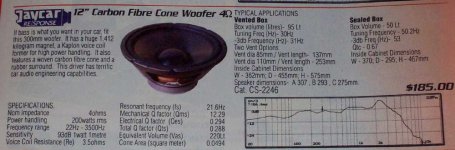
Here are the specs (attached image)! They sell this one (4ohm) as a car subwoofer but sell the 8ohm version as a hifi subwoofer, go figure... I'm not into car audio, I bought it as a hifi subwoofer, just havn't gotten around to doing anything with it.
I was thinking of trying something similar to this:
http://www.cowanaudio.com/hornsubjr.html
How would this go do you think? GM you say this is not really suited to a horn, is the result low efficiency or poor frequency response? If I got 35-80hz out of it I think I would be happy enough...
Would I be better off building a vented box? That isn't what I want though, distortion and low efficiency
I'm currently in the process of learning McBeans horn response, I havn't been able to find an FAQ or user manual, and some of the driver parameters seem a bit hard to obtain, is there a help page anywhere (online help is useful but rather brief)?
thanks, DB
Attachments
Hi!
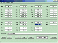
I have just copied the model from http://www.cowanaudio.com/hornsubjr.html and input my driver parameters. I had a guess for the ones I wasn't sure of...
The parameters I used are in the file below:
I have just copied the model from http://www.cowanaudio.com/hornsubjr.html and input my driver parameters. I had a guess for the ones I wasn't sure of...
The parameters I used are in the file below:
Attachments
broughd said:Hi!
I have just copied the model from http://www.cowanaudio.com/hornsubjr.html and input my driver parameters. I had a guess for the ones I wasn't sure of...
The parameters I used are in the file below:
I'm not sure how correct that simulation is. The 0.5Pi value means that the horn is in a corner. Still he adds a conical part that simulate the corner. As far as I can understand it, the last part of the horn should be removed, or the Pi value changed.
Frode
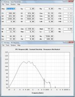
By the way, Hornresp can calculate many of the drivers values. Just doubleclick on the value you want to calculate. Start by putting in the Sd, then doubleclick Cms and so on. Do the values on the upper line first.
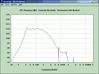
Here's how it looks with the values calculated for the Jaycar, and the horn without the last section.
Frode
Here's how it looks with the values calculated for the Jaycar, and the horn without the last section.
Frode
Attachments
Just to-nite on the drive home i was wondering what shape Ron would come up with for the "perfect" supraBaffle
There is no perfect. Just one with enough frontal area to support whatever given wavelength. The "tail" should be long enough to attenuate the wave, however you never get total attenuation. B&W has the correct ideas despite what their speakers sound like.
The 2" L trailing edges are a start. Now the edges project the diffraction rearward. The wave now is a secondary transducer (edges of trailing edge)with a later timed wave being projected rearward. This wave ,although weaker, is still present and will reflect off walls and such. In math you cannot attenuate to zero.
Its like a half life, you never reach zero.
This is getting into aerodynamics. I sim less diffraction (and weaker later timed wave) if the trailing 2" edges are angled to the rear of the cab and the front baffle is as spherical as possible, but still supports the required wave.. The only pratcial way i see to achieve this shape is fiberglass.
Now one thought is to position small reflectors of sufficent height along the taper. The energy would still be there but be dispersed. I see no energy being reflected from the rear taper edges and returning to the front baffle. Its more a rear projected wavefront.
ron
(let me work on this)
ronc said:There is no perfect.
Why i put it in quotes...
Now one thought is to position small reflectors of sufficent height along the taper.
EnABL spots?
dave
- Status
- This old topic is closed. If you want to reopen this topic, contact a moderator using the "Report Post" button.
- Home
- Loudspeakers
- Full Range
- Bruce + subwoofer