Just completed this project a couple of weeks ago.
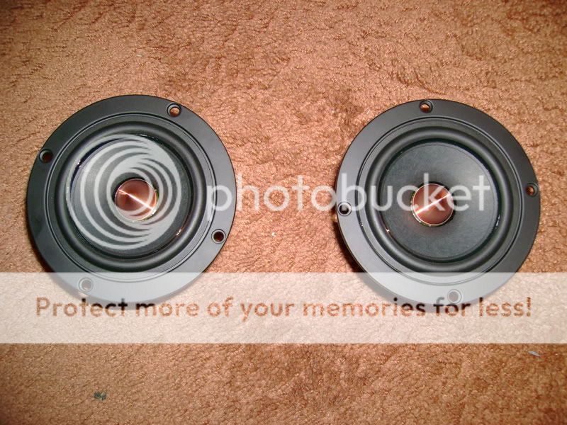
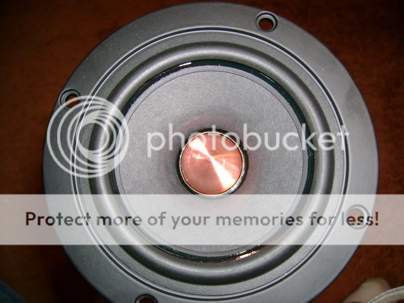
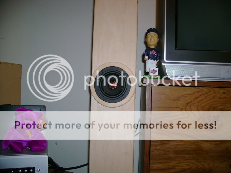
I am using the Creative Sound Solutions FR125S 4.5" full range driver in this design.

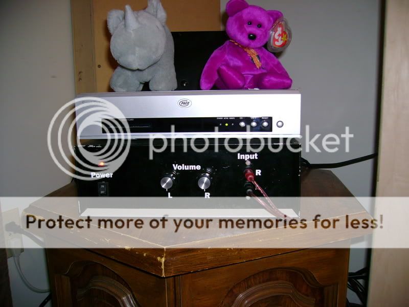
It is being powered by a DIY amplifier I made in tech school.
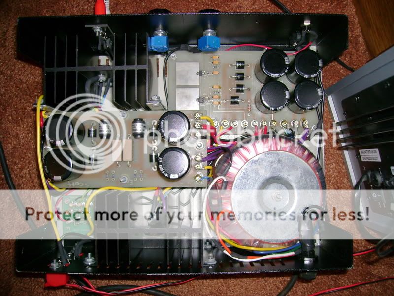
Documentation of the Amplifier
Did some quick measurements of the amplifier.
Equipment
Test #1: This test will full power test each channel separately for comparison with the all channels test to follow.
All verified with the Fluke RMS multimeter.
Test #1
Left Channel
17.6 Vrms into a 4 ohm load: 77.44 Wrms
19.2 Vrms into a 8 ohm load: 46.08 Wrms
Right Channel
17.6 Vrms into a 4 ohm load: 77.44 Wrms
19.2 Vrms into a 8 ohm load: 46.08 Wrms
Test #2
Left Channel
17 Vrms into a 4 ohm load: 72.25 Wrms
*** Vrms into a 8 ohm load: *** Wrms
Right Channel
17 Vrms into a 4 ohm load: 72.25 Wrms
*** Vrms into a 8 ohm load: *** Wrms
Conclusion
The amplifier much preferred powering the 8 ohm resistive load, as the numbers show. Typically, an amplifier will double the power output when the load is halved. In this case, it did not. This could be associated to the transformer or power supply being undersized or the input voltage not being constant as I do not have a variac to keep the circuit from loading down. I am confident that the power supply was not able to supply the amplifier with the required output to properly drive the 4 ohm load, as the all channels test shows, the power output does not dip very much at all when the transformer and power supply is powering both channels at full output power & I know the input voltage would not be loaded down enough to limit power output like that.
I was happy to see that the output of both channels match for all tests.
I was unable to test the 8 ohm all channels power test due to not having enough high power resistors to make two 8 ohm loads. I will pick up more & complete the test at a later date.
During the 4 ohm operation, all components stayed cool, but there was a slight ~1kHz oscillation that I could hear coming from the amplifier when the output got very close to clipping. This oscillation disappeared when the 8 ohm load was introduced.
I would conclude that, while this amplifier can power a 4 ohm impedance perfectly fine, you will not gain anything by using it to drive this lower load.
Please read this to find out why.
Therefore, using this amplifier with an 8 ohm load vs. 4 ohm load will result in not only better performance, but a lower current draw, less internal component noise, cooler operation & a longer life.
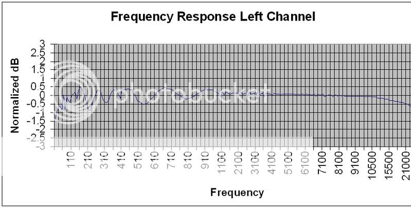
I also completed a quick frequency response measurement of the left channel.
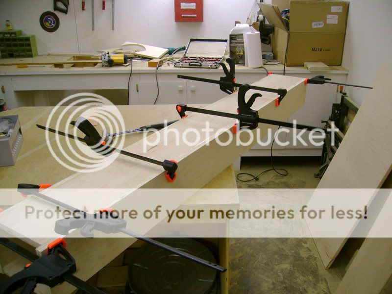
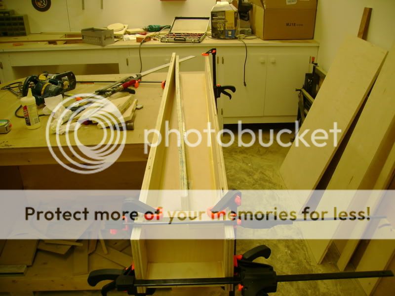
Now for some build pictures!
Only screws used are to mount the drivers to the baffle.


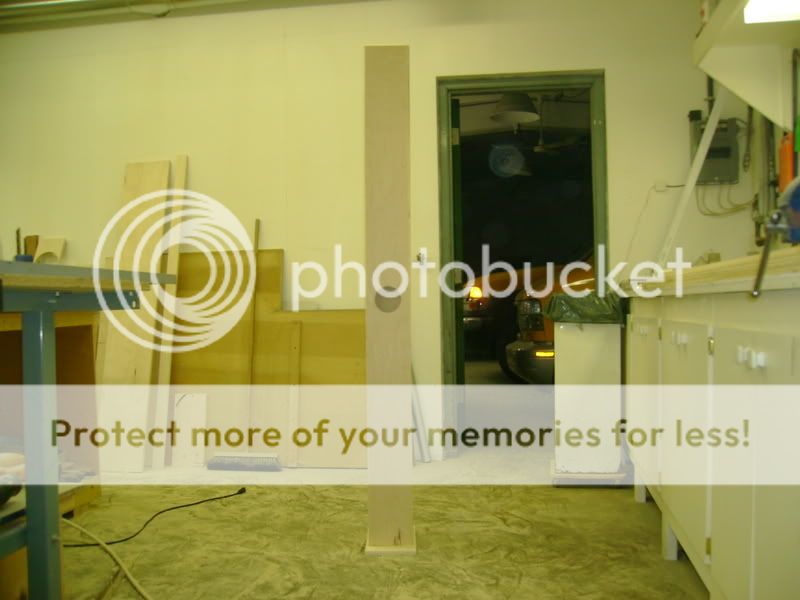

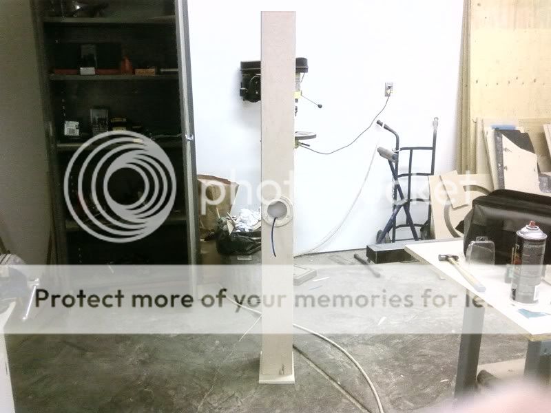
Tower #1 complete. Tower #2 looked the same while building")
Completed pictures.
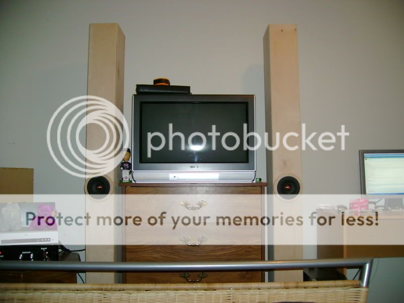
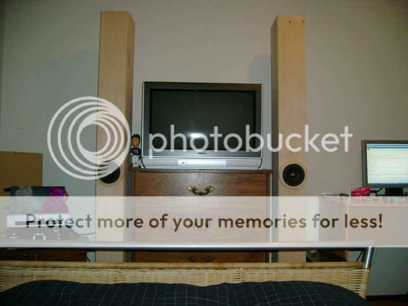

Listening area is temporary, but comfortable
I am using the Creative Sound Solutions FR125S 4.5" full range driver in this design.
It is being powered by a DIY amplifier I made in tech school.
Documentation of the Amplifier
Did some quick measurements of the amplifier.
Equipment
- Hewlett Packard 4935A Transmission Test Set
- Tektronix TDS 3032B Digital Oscilloscope
- Fluke 189 True RMS Multimeter
Test #1: This test will full power test each channel separately for comparison with the all channels test to follow.
- Connect a 4 ohm resistor load to the left channel output.
- Connect the transmission test set, which will be set with a 0dB 1kHz sine wave to the left channel.
- Measure RMS voltage across the load resistors at the point of clipping with both the oscilloscope & the RMS multimeter.
- Repeat for the right channel.
- Repeat with a 8 ohm load.
- Connect a 4 ohm resistor load to the left & right channel outputs.
- Connect the transmission test set, which will be set with a 0dB 1kHz sine wave to both channels.
- Measure RMS voltage across the load resistors at the point of clipping with both the oscilloscope & the RMS multimeter.
- Repeat with a 8 ohm load.
All verified with the Fluke RMS multimeter.
Test #1
Left Channel
17.6 Vrms into a 4 ohm load: 77.44 Wrms
19.2 Vrms into a 8 ohm load: 46.08 Wrms
Right Channel
17.6 Vrms into a 4 ohm load: 77.44 Wrms
19.2 Vrms into a 8 ohm load: 46.08 Wrms
Test #2
Left Channel
17 Vrms into a 4 ohm load: 72.25 Wrms
*** Vrms into a 8 ohm load: *** Wrms
Right Channel
17 Vrms into a 4 ohm load: 72.25 Wrms
*** Vrms into a 8 ohm load: *** Wrms
Conclusion
The amplifier much preferred powering the 8 ohm resistive load, as the numbers show. Typically, an amplifier will double the power output when the load is halved. In this case, it did not. This could be associated to the transformer or power supply being undersized or the input voltage not being constant as I do not have a variac to keep the circuit from loading down. I am confident that the power supply was not able to supply the amplifier with the required output to properly drive the 4 ohm load, as the all channels test shows, the power output does not dip very much at all when the transformer and power supply is powering both channels at full output power & I know the input voltage would not be loaded down enough to limit power output like that.
I was happy to see that the output of both channels match for all tests.
I was unable to test the 8 ohm all channels power test due to not having enough high power resistors to make two 8 ohm loads. I will pick up more & complete the test at a later date.
During the 4 ohm operation, all components stayed cool, but there was a slight ~1kHz oscillation that I could hear coming from the amplifier when the output got very close to clipping. This oscillation disappeared when the 8 ohm load was introduced.
I would conclude that, while this amplifier can power a 4 ohm impedance perfectly fine, you will not gain anything by using it to drive this lower load.
Please read this to find out why.
Therefore, using this amplifier with an 8 ohm load vs. 4 ohm load will result in not only better performance, but a lower current draw, less internal component noise, cooler operation & a longer life.
I also completed a quick frequency response measurement of the left channel.
Now for some build pictures!
Only screws used are to mount the drivers to the baffle.
Tower #1 complete. Tower #2 looked the same while building
Completed pictures.
Listening area is temporary, but comfortable
Lot more than just a BIB build going on here, eh? How does it sound? Do you have other speakers that you could hook up to your new amp so that you could possibly identify what is good/bad about the amp and what is good/bad about the speakers?
Really sweet looking build.
Kensai
Really sweet looking build.
Kensai
tinitus said:
I suppose when looking at driver size it really is a BIB ... should it really be that long ... I have a pair of drivers, maybe thats the one to do ... I only need the dimension
Oops, forgot to include the dimensions.
Internal dimensions
Height: 68"
So: 36.5"
Width: 4.75"
Depth: 7.25"
A,B,C: 3 5/8"
Sm: ~34.5 in^2
Kensai said:Lot more than just a BIB build going on here, eh? How does it sound? Do you have other speakers that you could hook up to your new amp so that you could possibly identify what is good/bad about the amp and what is good/bad about the speakers?
Really sweet looking build.
Kensai
The listening area is pretty temporary, going to be moved into the living room soon here. Sound-wise. I am in love with them. The low end impact is very impressive, and with a little EQ work, the high end really shines. I use them for both music & movie duty, and I haven't found any material that leaves me feeling I'm missing something.
IMO nothing beats a good full range driver configuration. As is, with the current placement, the listening sweet spot is pretty narrow, as expected.
I'll get back to you on more thoughts on the amplifier in the coming months. Once these BIBs are moved, I am likely going to try out the new Peerless 2" full range driver in something a little smaller for the bedroom.
tinitus said:Link to amp documentation does not work
It will in a bit. My host is experiencing some routing issues at the moment.
Hey man,
Did you take the electronics enginnering technology course in Moose Jaw?
I took that course and it looks like the same amp as we built. There are a few mods you can do to improve it, like find a dual ganged volume pot that will use just the one knob to change volume. I find the pots that Rob used which are standard linear pots have a ~1mm spot where they go from quiet to very loud with not much getting louder after that. Try this one maybe. http://search.digikey.com/scripts/DkSearch/dksus.dll?Detail?name=P2Y7503-ND
It is a totally dc coupled amp so you want to make sure the dc voltage level on the incoming source is very low. Even 1mV will put 30 mV out to the speakers due to the gain. This could be reduced with a capacitor in the feedback path or a input capacitor.
Other than that, the amps all right. It has excellent low end response because it is flat to dc, but it could be upgraded with a rebuild to a lm3886 or something similar and possible increase the transformer, then you could hit the full ~ 90 watts into 4 ohms that it is supposed to do. The slew rate of the lm12cl or what ever the chip is is very low.
Its nice to see another person from Saskatchewan on here.
davidallancole said:Hey man,
Did you take the electronics enginnering technology course in Moose Jaw?
I took that course and it looks like the same amp as we built. There are a few mods you can do to improve it, like find a dual ganged volume pot that will use just the one knob to change volume. I find the pots that Rob used which are standard linear pots have a ~1mm spot where they go from quiet to very loud with not much getting louder after that. Try this one maybe. http://search.digikey.com/scripts/DkSearch/dksus.dll?Detail?name=P2Y7503-ND
It is a totally dc coupled amp so you want to make sure the dc voltage level on the incoming source is very low. Even 1mV will put 30 mV out to the speakers due to the gain. This could be reduced with a capacitor in the feedback path or a input capacitor.
Other than that, the amps all right. It has excellent low end response because it is flat to dc, but it could be upgraded with a rebuild to a lm3886 or something similar and possible increase the transformer, then you could hit the full ~ 90 watts into 4 ohms that it is supposed to do. The slew rate of the lm12cl or what ever the chip is is very low.
Its nice to see another person from Saskatchewan on here.
Dave!
It's Scott!
Small world haha.
- Status
- This old topic is closed. If you want to reopen this topic, contact a moderator using the "Report Post" button.
- Home
- Loudspeakers
- Full Range
- FR125S BIB Project