I wander how many people are interested to play with exaU2I and DSD? I haven't heard back form Flemming and I have no further details on the player ->ASIO wrapper setup that was used for his experiment. There are two options to enable DSD with exaU2I:
This is exactly what I have been waiting for, I really hope you can make it happen!
Email issues have been sorted out and I have received and compiled Flemming's DSD player prototype. I will be working on it when I come back from vacation.
Ok Exa065 so I 've got a Buf32s which I'm currently driving with Juli@ I2s. Now if I wanted to use your product and use some of the crossover capability how would I do it? Do I need another buf32s?
Well, you have one I2S source and if you add an exaU2I to the mix you will need to switch between I2S sources somehow. You can use one or the other.
Then you need to decide on crossover software. Are you going to use a VST plug-in like Allocator? If yes you need a VST host. I have a demo setup described here.
Are you going to be using 3-way or 4-way speakers? If you have "a Buf32s" than I assume you have a 2 channel DAC. For a 3 way system you need total of 3 Buffalo II DACs.
Native dsd playback from WinXP PC using the exaU2I
Hi Flemming,
Finally I've managed to get back to my office and to experiment with your proof-of-concept DSD player. Actually it works great! I enjoyed the full glory of the DFF downloads from 2L. Thank you for pioneering this exciting development.
My next step is to research the possibilities for creating a user friendly solution for DSD playback. Any feedback is welcome.
exa065
About 2 weeks ago when I again was looking for dsd support for the exaU2I, I started thinking about the similarities between I2S with 32 bit data length and raw DSD.
I2S has a bit clock of 64*Fs, a Fs word clock and two 32 bit data words for a stereo channel
Raw DSD has a bit clock of 64*Fs, a Fs word clock (not allways used) and a data rate of 64*Fs for each channel
So an quad 44.1kHz I2S connection will have the data rates needed for a raw dsd connection to a if we connect like shown below.
I2S dataclock -> DSD data clock (Data clock)
I2S data channel 1/2 -> DSD data 1 (D1)
I2S data channel 3/4 -> DSD data 2 (D2)
I2S wordclock -> not connected
Note it will only work because exaU2I support 32bit data, two+ I2S data channels , and the ESS9018 dac do not use the wordclock for DSD data.
So I ordered an exaU2I
I got the exaU2I unit this Friday and started playing with the software using the C# Asio wrapper from here Low Latency Audio using ASIO Drivers in .NET - CodeProject as a starting point.
I am now listening to Alison Krauss's Live album in DSD playing back from my WinXP PC
If anybody will like to try, I will be happy to supply the software, but "as is".
It is only a proof of concept and have to be used with extreme care.
I also tested that the ES9018 have support for both DSD64 and DSD128
Flemming
Hi Flemming,
Finally I've managed to get back to my office and to experiment with your proof-of-concept DSD player. Actually it works great! I enjoyed the full glory of the DFF downloads from 2L. Thank you for pioneering this exciting development.
My next step is to research the possibilities for creating a user friendly solution for DSD playback. Any feedback is welcome.
exa065
it means that the sabre 901X series dacs do not have an internal i2s mux, only spdif sources can be switched using only the dac and its mcu. if you have 2 i2s sources connected at once they will just play over each other, as with i2s and spdif. you need an external way of switching between the 2 sources and the output of that switch is connected to the dac. you can use something as simple as a couple of relays, or you can do it by fully software driven means.
Ok yes thank you I do understand what you are saying but what connection or relevance does that have with using the exa21 as an electronic x-over? Don't I need to just come out of the exa21 to 2 different dacs one for the high pass filter one for the low pass filter assuming a 2 way?it means that the sabre 901X series dacs do not have an internal i2s mux, only spdif sources can be switched using only the dac and its mcu. if you have 2 i2s sources connected at once they will just play over each other, as with i2s and spdif. you need an external way of switching between the 2 sources and the output of that switch is connected to the dac. you can use something as simple as a couple of relays, or you can do it by fully software driven means.
Ok yes thank you I do understand what you are saying but what connection or relevance does that have with using the exa21 as an electronic x-over? Don't I need to just come out of the exa21 to 2 different dacs one for the high pass filter one for the low pass filter assuming a 2 way?
I think there was an assumption from your post that you wanted to continue using the Juli@, which led to the discussion about source switching. Just ignore that bit and pay attention to the questions about x-over software.
Ok yes thank you I do understand what you are saying but what connection or relevance does that have with using the exa21 as an electronic x-over? Don't I need to just come out of the exa21 to 2 different dacs one for the high pass filter one for the low pass filter assuming a 2 way?
Here is your minimal configuration:
- Multichannel I2S source: Juli@ or exaU2i
- Two Buffalo II DACs for a two-way system.
- Software crossover to split 2 channel source into four output channels
- Player or VST host, or the combination of the two to host the crossover
Actually, since the B-III can be configured as up to 8-channels, you can get by with a single B-III (without the benefits of the combined channels, of course).
Hi Brian, Is the B-III available now?
Hi Brian, Is the B-III available now?
Not yet, but the B-II is no longer available. I think we will start pre-orders in a couple weeks.
Actually, since the B-III can be configured as up to 8-channels, you can get by with a single B-III (without the benefits of the combined channels, of course).
so its a matter of feeding the 8 x dsd pins discretely, or the 4 x stereo pcm channels yes? (aside from spdif of course)
Not yet, but the B-II is no longer available. I think we will start pre-orders in a couple weeks.
Could you share with us how DSD can be interfaced with Buffalo-III?
Could you share with us how DSD can be interfaced with Buffalo-III?
Just supply the DSD Data_clock and DSD data lines to the input header. Termination is already there.
If you are using fewer than 8-channels, you can join DSD inputs via jumpers under the board as needed. Same for PCM input.
Here is your minimal configuration:
Do you have any specific questions on any of these items?
- Multichannel I2S source: Juli@ or exaU2i
- Two Buffalo II DACs for a two-way system.
- Software crossover to split 2 channel source into four output channels
- Player or VST host, or the combination of the two to host the crossover
No I'm ok now. I use cplay which can use a vst. Just wanted to confirm that I would need the exaU21 and another Buf32s. Thanks
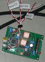
The pictures shows where the USB power trace from the USB connector are cut, and where the new 5 volt are connected to supply the USB parts.
The quality of the pictures are not the best, but they will have to do.
On the exaU2I there are also two other places I have cut traces.
The PCB trace going from the 5 volt (USB) to the 3.3 and 1.2 volt onboard regulators and the PCB trace close to the 1.2 volt regulator and reconnecting it to be supplied from the 3.3 volt.
I am very interested in learning more about your exa tweaks. I cannot tell where you cut the traces on the exa board (from your pics)
so that you could supply LiFepo4 power to it. Can you say more about it please? I have a juli@ powered by 3 LiFepo4's and and a Buf32s powered by 3 LiFePo4's (all into the digital ps) so if I get an Exa I could do this too. Based on this thread I am very interested in the ExaU21 for a straight Juli@ replacement then to use eventually in conjunction with a digital crossover.
I run cplay/cmp.
The last change I did to the exaU2I was a 5 volt JFET regulator for the USB parts that was optimized for 6.6 volt input (LiFepo4 *2).
The 5 volt are normally feeding the 3.3 and 1.2 volt regulators.
This connection was cut and the 3.3 volt regulator was bypassed so a LiFepo4 battery could drive the 3.3 volt line directly and feed the 1.2 volt regulator, a reconnecting of the 1.2 volt regulator input are needed.
The GMRs was supplied with a third LiFepo4 3.3 volt source.
You will easily find the 5 volt trace coming from the USB 5 pin connector as it goes directly to a through hole (large) connection between the two PCBs.
I cut the USB 5 volt between those two locations.
On the lower (main) PCB I cut the 5 volt after the decoupling capacitor close to the through hole connection.
The picture does not show all the decoupling capacitors as some of them are located under the PCB.
The exaU2I in the picture had the three LiFepo4 inputs / connections labeled for easy connection / setup due to it was about to be sent to Bulgaria..
PS! In my setup I do not use LiFepo4 anymore as I use JFET regulators and a extremely good linear power supply that outperforms the LiFepo4..
But this is a "cost no object" setup and not available to any other than me...
Attachments
- Home
- More Vendors...
- exaDevices
- exaU2I - Multi-Channel Asynchronous USB to I2S Interface