Hi all, this is my first post so please accept my appologies as I'm not sure if this is the correct place to seek help.
Firstly, I'm not a total stranger to electronics and I'm able to read schematics, breadbard them and make my own PCBs etc, however I lack the experience when it comes to designing and the therory side of things, which is why I'm seeking some help.
I'm using a PIC micro as a base for a disco light controller. I've managed the basics such as programming the patterns into the PIC etc, but now I'm stuck with the music section.
I'm trying to build a base beat trigger, so that I can step the pattern to the beat of the music. The theory I had was to use a low pass filter based on a TL81 / 82, which is then used to trigger an NE555 so that this gives a nice clean 5v logic pulse which I can feed into the PIC. However I've spent hours searching the net and can't find anything that presents a decent schematic (most sites just give shed loads of formula for working out the gain, etc of the op amp).
I did try building one similar circuit I found a few months ago, but that failed to work, so if anyone can offer a schematic of a decent bass beat extractor (with component values if possible) it would be great.
Cheers
Malcolm
I've used this LPF before for my subwoofer,except I used a TL072/82 op-amp.It works nicely.
http://www.users.qwest.net/~ptaylor/Audio/xover-2.jpg
http://www.users.qwest.net/~ptaylor/Audio/xover-2.jpg
djQUAN said:
Tried that one and it doesn't work. I e-mailed the chap and he couldn't shed any light on it as he didn't actually design it and has lost contact with the original author. It just seems that a lot of the "modules" are just theory, and nothing other than the basic dimmer section was ever built.
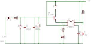
I have however come up with the attached, which provides excellent beat recognition, however it also seems to cause the PIC micro I'm using to re-set, even though there is no direct connection between the output of the ne555 and the micro. Its as though the supply is constantly being pulled low everytime the peak LED on the NE555 is lit, although I can't see any reason for it, and test still show the supply voltage no lower than 4.6v
Could it be that the PIC has a config that could be set to stop it resetting, or is the filter design flawed ?
Cheers
Malcolm
Attachments

- Status
- This old topic is closed. If you want to reopen this topic, contact a moderator using the "Report Post" button.
- Home
- General Interest
- Everything Else
- Bass beat filter