I've come up with this for a combination DC protection/Speaker delay/clipping indicator. I'd originally hoped to this on a single board with a power controller/soft start circuit, but I couldn't do within the free EAGLE board size limit without going SMD. I really don't want to go SMD, so it is two boards. (The controller should be published soon)
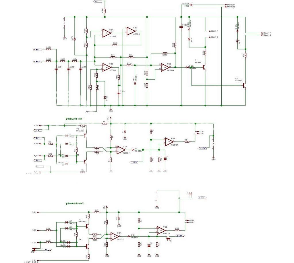
This board consists of two of Rod Elliot's project 23 clipping indicators and a copy of the Hafler DC protection/speaker delay circuit. All are powered by the amp's rails, although the relay power is separate and could easily be powered by an auxiliary power source. Power for the clipping indicator opamps can come from a +12V supply or the amp rails.
Each clipping indicator has two inputs and is completely independent. The power rails can be tied together if the amp has a common supply. One input from the first clipping indicator can be routed to the other so that a single connector can be used to bring power and signal to the board.
Options include:
Single clipping LED for
1. up to four channels with a common PSU
2. two channels with independent supplies. (dual mono)
3. 4 channels with two power supplies (dual stereo)
2 clipping indicators for
1. 2-4 channels with a common power supply.
2. 2-4 channels sharing two power supplies.
The protection circuit is pretty much a straight copy of the hafler circuit. Keeping the input resistors different means that the circuit will open the speaker relays if the two channels fail to opposite rails.
Since the circuit is rail powered, when the rails come up it delays closing the speaker relays for a few seconds.
I made two changes to the circuit:
I doubled up the relay control transistors so I can be comfortable using two relays to control a four channel amp. High hfe BC546C should ensure that the LM339 has no trouble driving a pair of relays. I plan to use this with a 4 channel amp that shares a common supply.
My mains power is subject to blinking in the summer - it cuts out just long enough to cause thumps in my system, but not long enough to open the speaker relay on my DH500. Taking a cue from Rod Elliot, I added a spot for zeners in series with the protection diodes across the relays. This should make the relays open a little more quickly.
As I write this up, I realize that I don't have DC protection on two of the inputs. I'll add that but in the meantime comments, constructive criticism and suggestions welcome.
Schematic -
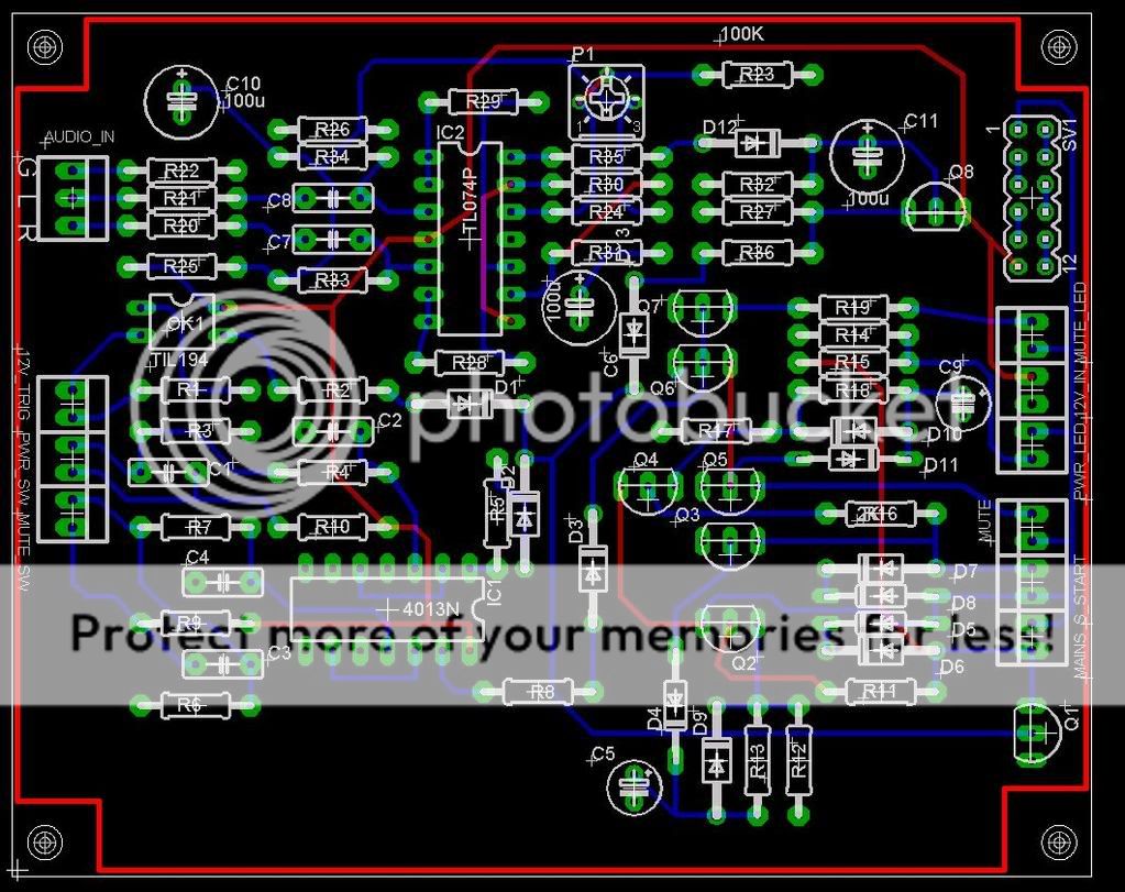
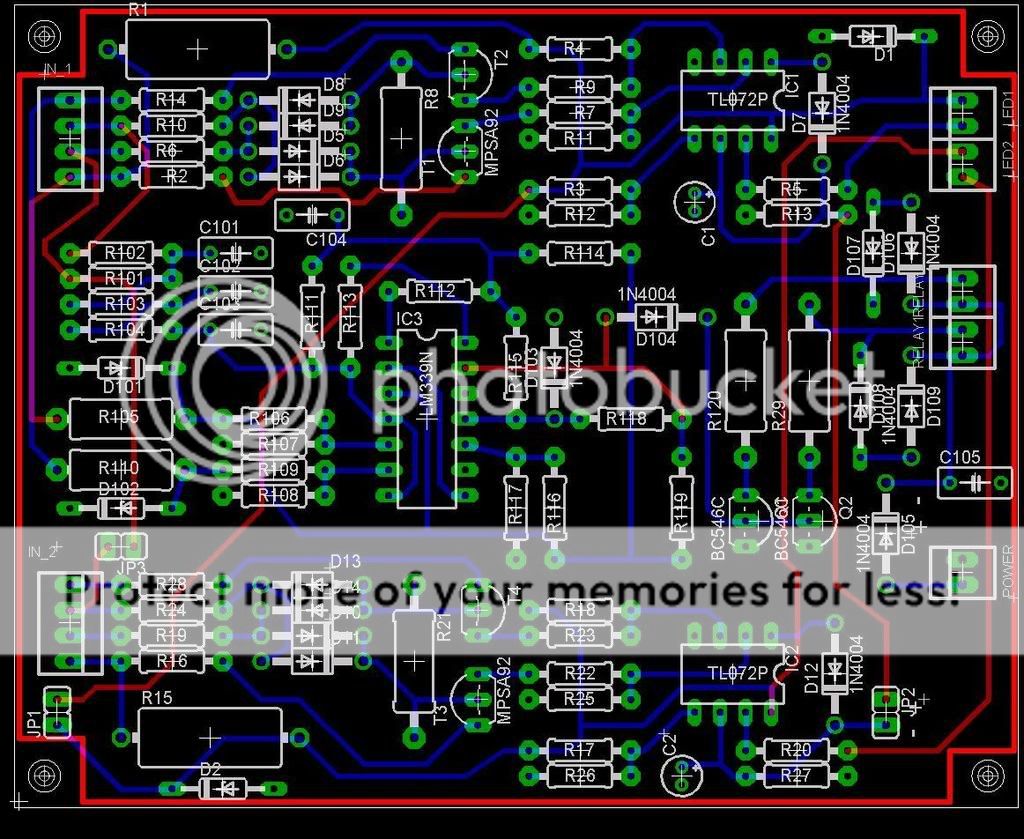
Board layout minus the ground plane -
This board consists of two of Rod Elliot's project 23 clipping indicators and a copy of the Hafler DC protection/speaker delay circuit. All are powered by the amp's rails, although the relay power is separate and could easily be powered by an auxiliary power source. Power for the clipping indicator opamps can come from a +12V supply or the amp rails.
Each clipping indicator has two inputs and is completely independent. The power rails can be tied together if the amp has a common supply. One input from the first clipping indicator can be routed to the other so that a single connector can be used to bring power and signal to the board.
Options include:
Single clipping LED for
1. up to four channels with a common PSU
2. two channels with independent supplies. (dual mono)
3. 4 channels with two power supplies (dual stereo)
2 clipping indicators for
1. 2-4 channels with a common power supply.
2. 2-4 channels sharing two power supplies.
The protection circuit is pretty much a straight copy of the hafler circuit. Keeping the input resistors different means that the circuit will open the speaker relays if the two channels fail to opposite rails.
Since the circuit is rail powered, when the rails come up it delays closing the speaker relays for a few seconds.
I made two changes to the circuit:
I doubled up the relay control transistors so I can be comfortable using two relays to control a four channel amp. High hfe BC546C should ensure that the LM339 has no trouble driving a pair of relays. I plan to use this with a 4 channel amp that shares a common supply.
My mains power is subject to blinking in the summer - it cuts out just long enough to cause thumps in my system, but not long enough to open the speaker relay on my DH500. Taking a cue from Rod Elliot, I added a spot for zeners in series with the protection diodes across the relays. This should make the relays open a little more quickly.
As I write this up, I realize that I don't have DC protection on two of the inputs. I'll add that but in the meantime comments, constructive criticism and suggestions welcome.
Schematic -
An externally hosted image should be here but it was not working when we last tested it.
Board layout minus the ground plane -
An externally hosted image should be here but it was not working when we last tested it.
roughBOM
Semis:
1n4007 – 10
1n4148 - 4
1n5242 – 4
1N5240 – 2
BC546C – 2
MPSA42 – 4
MPSA92 – 4
TL072 – 2
LM339 - 1
Caps:
1 µf 16V – 2(shown as a film cap - may jsut keep it that way for .07 difference)
.39 µf – 3
10 µf 16V NP – 1 C104 shown as a film cap - needs to change.
22 µf 100V - 1 - C105 shown as a film cap - needs to change.
Resistors:
1K – 10
100K – 9
27K 1W – 2 (value depends on rail voltage)
2K7 2W – 2 (value depends on rail voltage)
12K – 4 (value depends on rail voltage)
150K – 8
27K ½ W – 2
22K – 3
3K9 – 2
1M – 1
10M – 2
4K7 – 1
1k5 2W 2 (value depends on rail voltage)
2 Pin Headers or Molex 2 pin KK headers – 5
4 Pin headers or Molex 4 pin KK headers – 2
I figure under $10 for parts. Add your relays to this. I plan to use flange mount relays so no board required.
🙂
Great work
and a very useful circuit for all us amplifier builders.
It has those basic functions for protection we can benefit from,
if we care for our projects and speakers to be a little more safe.
And do not want those bad troubles.
At least those which can be avoided.
Thanks for sharing BobEllis.
Can't be too difficult to build, for those who can make or some way get PCB for it.
Of course there has to be some instructions added
so we know how to setup and adjust parameters.
But I guess we will get this knowledge by and by
if we keep on asking questions in this dedicated topic.
Regards
lineup 😎
Thanks for the encouragement, Lineup. I plan to have our friends at Advanced Circuits make me some boards. If there is enough interest I could do a group buy of boards and parts.
I've had an offer to integrate the soft start/power controller part of my idea into a single board by someone with a full copy. I'm working on that now. The features I plan to incorporate there are:
Soft start - including thermal shutdown if soft start relay fails.
Power on with either
1. Momentary pushbutton
2. 12VDC trigger
3. audio input
Second delay to drive muting relays - initiates when soft start trips.
Momentary pushbutton mute relay control.
Connections for thermal fuse protection - kills main power when overtemp exists. You'll be able to use several sensors or jumper them out if not needed.
Standby/ power on LED
On-board transformer for aux power.
I'm thinking that I will score the boards between the soft start section and the clipping/DC protect circuit so they can be mounted separately if desired. (or eliminate the clipping indicator for preamp use) I'm wondering if it might make sense to make one large panel with the muting relay circuits too. Have all sections scored and ready to break apart - it might make production more cost effective.
Thoughts? Missing features?
BobEllis said:Thanks for the encouragement, Lineup.
I plan to have our friends at Advanced Circuits make me some boards.
If there is enough interest I could do a group buy of boards and parts.
BobEllis.
Wait for some time with those good plans of Group Buy and making some boards.
Let this topic run for some weeks.
Like with software, there is always good with some debugging period.
Before an official public STABLE release.
1. Alpha versions
2. Beta versions
3. Release Candidate versions, RC1, RC2 ..
4. Release
5. Release fixes and patches
My guess is that this Protection and Clipping Indicator Circuit
is in stage 2. Beta or possibly in stage 3. RC1 = Release candidate 1
---------------------------
As I say, if people will have a good look at your circuit
and suggest modifications for improvements
and so avoiding problems in some unusual situations,
you might have a very good release version in some weeks or a couple of months.
Of course, the most of debug and testing you will do yourself.
Using other amplifiers with different power supply and various levels of everything.
Just because everything works with one amplifier, doesn't mean it will work like this in another.
It may work, if it is a very good and flexible circuit.
But until some further testing and other people have had a look at it,
we cant know.
I know you wont take this as critics, from me.
I only wish the best for any good project.
It is just so much better, to make sure circuits are 95% reliable
and works in >=90% of all cases
before start make and offer PCB to other people.
Regards
lineup
Hi Lineup -
I appreciate your suggestions. I am nowhere near ready to order anything like a production board. I was just trying to publicly outline my intentions for this project.
Since the circuits presented here already are basically copied from others, I think they are fairly close to being releaseable. I will breadboard them over the next few weeks.
The rest of it will be lifted from application notes. I have no formal electronics education, so I will be looking for all the guidance I can get. I will breadboard the circuits before ordering prototype boards and test those before going to production. If I can get all the sections into a single panel that fits the size limits, I can take advantage of Advanced Circuits 3 for $33 each special - and have a prototype board set complete with soldermask and silkscreen.
I have found circuits that I plan to copy for using a 4013 flip flop for the pushbutton operation. Are the switches properly debounced? Have I connected it properly for startup in the powered down state? Hopefully someone in the know will check once I post a circuit.
The audio detect circuit will also be borrowed from Rod Elliot with the addition of buffers on each of the inputs. When I breadboarded the circuit I found that with my sound card the crosstalk was unacceptable as the circuit is published. I will add a bit of gain in the buffers since I found sensitivity too low.
The 12V trigger will use a TIL-194 AC transistor output optocoupler and a resistor to limit the current. This will help prevent ground loops. Pretty simple.
The flip flop, audio detect and 12V trigger will supply current (through diodes to isolate each) to the base of a BC546C to activate the mains relay. This will trigger the delay setup using a BC556C to drive the soft start relay. this will trigger the next delay to activate the muting relays. (I have thousands of both of these, so why not use them. 😉 )
I'd better get back to working on the schematic and post it for review.
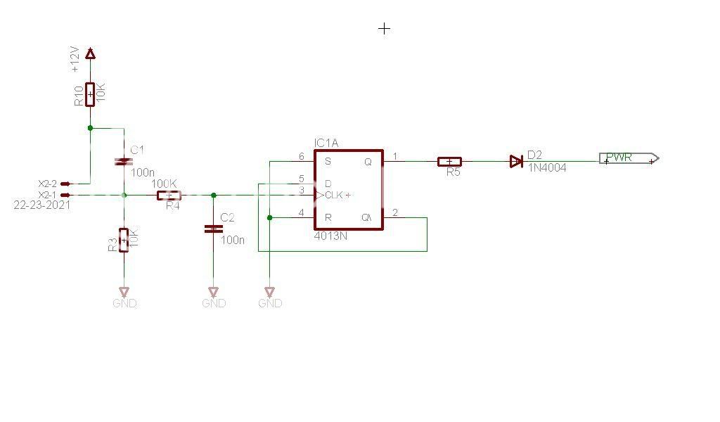
I'll post the schematic of the soft start portion in pieces to make it easier to read.
Here is the basic flip flop circuit that I plan to use for the power on/off and mute functions. Not shown is the implicit power connection. Does this seem reasonable and debounced? Will the output be low on initial power up?
The momentary switch connects to the header on the left. Teh port labeled power connectst to the relay driver.
What is the threshold/trigger voltage of the DC sense circuit?
Just an idea - what if a Leach style Clip indicator were to be used, it may be possible to sense overcurrent as well in most output configurations? If the sense circuit is made adaptable, this would be a very comprehensive protection board.
Another thought - let the relay drive be take off points on this board so that the relays can be located on the amp boards itself making for short signal paths and less heavy guage wiring.
The clipping indicator threshold can be set by adjusting component values. Rod uses 3V below the rails, I plan to use 5V for a little extra margin. See Project 23
I tried to wrap my mind around the Leach circuit since it has so few parts, but couldn't figure it out well enough to scale it for various rail voltages.
The DC protect threshold is 1.8V below 10 Hz, adjustable with resistor values should that prove too high.
I plan for all relays to be off board for exactly the reasons you describe. Pin Headers or Molex .100" KK series connectors can be used.
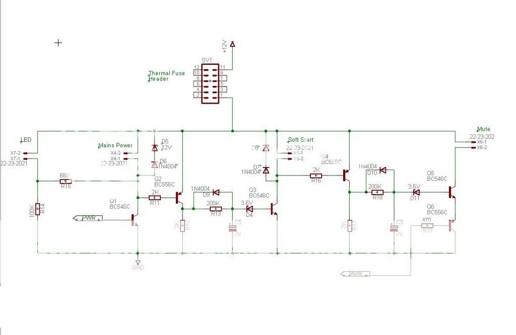
Here's the soft start part. It seems like the BCs with 400-800 hfe ought to be turned on hard enough to operate the relays. However I noticed that P-A darlington connects them. Any recommendations?
The part of this that is mine (and not just a ripoff) is the mute circuit. On power up the mute flip flop is low, connected to the base of Q6, turning it on. When the mute button is depressed, the output goes high, turning off Q6 and removing power from the mute relays.
Would it make more sense to make Q6 a BC546 and connect it between the base of Q5 and ground so that when the Mute flip flop output goes high it shunts the Q5 base current to ground?
Values in the LED circuit are TBD. The idea is that when power is applied to the soft start circuit there is just enough current through R14 to make the LED glow very dimly for a standby indication. When mains power is turned on the Q1 end of R15 goes low enough to allow more current to flow and the LED lights brightly. I found this in a circuit in this forum, but I cannot find it now.
The header allows connection of thermal fuses or temperature switches. I think that fuses should be used in home applications since it forces you to open up the amp and hopefully find out why it overheated. For PA applications it may make sense to use switches.
One fuse should be mounted near the soft start resistor. The others can be mounted on the output heat sinks, mains transformer or wherever you desire. Jumper the pads if not needed. I am undecided if this will be changed to a string of KK connectors for reliability. I guess it depends on the board space available when I lay it out.
Here is this part of the circuit.
EDIT: Yes, I realize that there are no protection diodes on the muting relay circuit. Since those relays will be on a board I plan to incorporate the protection diodes there.
The protection Zeners are backwards in this picture, corrected on the schematic.
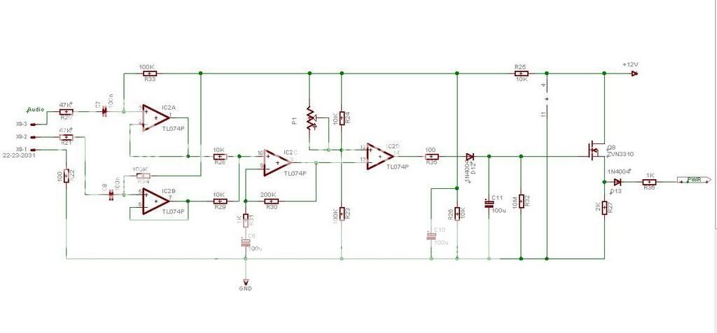
And finally, here is the audio detect part of the circuit.
It is Rod Elliot's Project 38 with input buffers added to prevent crosstalk, increased gain and provisions for a trimpot to adjust sensitivity. I also use a TO-92 MOSFET to switch the power turn on current instead of the TO-220. I'm thinking I can probably eliminate R27.
Time for some sleep.
It is Rod Elliot's Project 38 with input buffers added to prevent crosstalk, increased gain and provisions for a trimpot to adjust sensitivity. I also use a TO-92 MOSFET to switch the power turn on current instead of the TO-220. I'm thinking I can probably eliminate R27.
Time for some sleep.
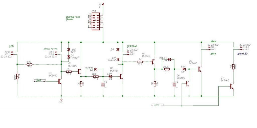
Slight revision to the soft start circuit.
- changed muting control
- added mute indicator LED circuit
I'm still working on laying this out.
Feedback?
- changed muting control
- added mute indicator LED circuit
I'm still working on laying this out.
Feedback?
My DAC's volume control is a motorized stepped attenuator. The only rotary switch I could get that was both quality yet cheap was a break-before-make type. In its configuration, shunting between inverted and non-inverted balanced signal after series resistance (so only two decks would control volume on a balanced stereo setup), means that when the break occurs, it would go to full volume. The solution was that the infrared monitoring of switch position would activate the mute relays during a transition (and also force the motor h-bridge driver to continue rotation until it clicked into the next position).
I'm having a problem with initial turn on, however, with the same muting relays. There's a very loud pop. Now, the DC offset is about 0.2 mV max, and there are I think 500k resistors to ground. So what gives? I can't understand how 0.2 mV would give such a huge pop. I'm listening to this with an OTL tube headphone amp with an input being a 100k to ground. Could somehow voltage be developing on the tube amp's input, despite the 100k resistor? The input is DC coupled to a grid.
I'm having a problem with initial turn on, however, with the same muting relays. There's a very loud pop. Now, the DC offset is about 0.2 mV max, and there are I think 500k resistors to ground. So what gives? I can't understand how 0.2 mV would give such a huge pop. I'm listening to this with an OTL tube headphone amp with an input being a 100k to ground. Could somehow voltage be developing on the tube amp's input, despite the 100k resistor? The input is DC coupled to a grid.
- Status
- Not open for further replies.
- Home
- General Interest
- Everything Else
- DC Protection and Clipping Indicator