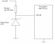
There are a lot of possibilities :
- resistor + zener diode (as above)
- use a transistor as an open collector (inverts the signal)
- 1Meg resistor and trust the IC's internal clamping diodes (haha)
- the professional solution : use a specialized IC from Max Semi (don't remember the part number right now)
If you want ot do it the other way (ie TTL -> 12V) the open collector is the simplest.
sivan_and said:"RussB" How can you be soo sure ..without knowing the load current ?
Hi SivanandBalan,
The clue was in the question "ttl". However, if people ask the wrong question, they'll get the wrong answer.
Sure, it wasn't an optimised solution, more information would be needed for that. This requirement needs a passive solution, active solutions will need their own supplies, packaging and so on. Sledgehammer/walnut?
Hey, I just registered, be gentle!
Russ
google "logic level translater" or "logic level shifter"
Do keep in mind that automobiles have a side effect known as "load dump". For a brief period when the ignition is shut off, a pulse of 60 to 400 Volts blasts through the 12 Volt bus. Not a huge problem, but just be sure you have some series resistance in your inputs to limit currents that flow through the protective diodes in your chips.
")
Do keep in mind that automobiles have a side effect known as "load dump". For a brief period when the ignition is shut off, a pulse of 60 to 400 Volts blasts through the 12 Volt bus. Not a huge problem, but just be sure you have some series resistance in your inputs to limit currents that flow through the protective diodes in your chips.
RussB wrote:
then change your "Biography"...you'r not as mentioned..Hey, I just registered, be gentle!
TTL means in this case Transistor-Transistor-Logic. Check parts like 74xx, 74LSxx etc.RussB said:
Hi SivanandBalan,
The clue was in the question "ttl". However, if people ask the wrong question, they'll get the wrong answer.
Sure, it wasn't an optimised solution, more information would be needed for that. This requirement needs a passive solution, active solutions will need their own supplies, packaging and so on. Sledgehammer/walnut?
Hey, I just registered, be gentle!
Russ
"1" > 1.4 volts
"0" < 0.7 volts
 Why writing being an idiot and have no interests
More info
I will be taking 12v signals from the car (either 12v or 0) and feeding that into a microcontroller (run off a 5v supply), so the currents will be very small).
Poobah, I did google those phrases, but most of the results were 5v to 3.3v converters. Is there a specific name for the 12v devices?
I will be taking 12v signals from the car (either 12v or 0) and feeding that into a microcontroller (run off a 5v supply), so the currents will be very small).
Poobah, I did google those phrases, but most of the results were 5v to 3.3v converters. Is there a specific name for the 12v devices?
Xplod,
http://www.onsemi.com/PowerSolutions/product.do?id=MC14504BCP
Don't be fooled by the fact the this says CMOS output only... It can be used for exactly this purpose. You just cinnect the output supply pin to your 5V. It really depends on the type of TTL you are using... regular TTL no... LS TTL yes.
Really, the circuits posted here are just as easy. In fact, when you consider you still need input protection... these circuits are probably simple to imlement.
Now... when you say 0 volts... do mean 0 Volts... or NO Volts, as in an open circuit? There is a diiference and TTL inuts will need a sink to ground to register a "low" state.
Do you want to just get the microcontroller to know if the car amp is on or off? If this is so, follow perander's suggestion... Check the microcontroller data sheet - most will switch logic states at the half voltage, i.e. 2.5V or greater is considered logic 1, anything below 2.5 is logic 0. If it's really "TTL" then anything from 2.0V to 5V is a logic 1, and 0.8V to 0V is logic 0.
Cheers
Cheers
Howdy,
Depends on the frequency of the signal. Using the parallel port, you might be able to monitor the presence of a signal, if the frequency is low enough... (or, with a high frequency, you'd probably miss a transition or two), but it should work. Serial would be more iffy, and USB - well, writing a driver to talk to the USB device is probably not worth the time - well, unless someone else already has...
Cheers
Thanks for the reply.
My current thinking is to put the signal (130Hz max) to pin-10 of the parallel port (ACK) and monitor with an interrupt (IRQ 7).
With TTL "high" being 2.4v-5v, a 100-ohm resistor and 7.5V Zener should do the trick, no?
It's an OLD laptop, but I'd still rather not fry parallel port.
Doug
My current thinking is to put the signal (130Hz max) to pin-10 of the parallel port (ACK) and monitor with an interrupt (IRQ 7).
With TTL "high" being 2.4v-5v, a 100-ohm resistor and 7.5V Zener should do the trick, no?
It's an OLD laptop, but I'd still rather not fry parallel port.
Doug
It "should" but I'd opine that it isn't the safest solution. If ever the signal goes above 12V, (i.e a transient), you may still zap the parallel port. Also, if the zener were ever to fail (again, perhaps due to a transient), it can fail as a short, and there again goes the port.
I think a resistive divider is safer. Use values to get the 12V down to about 3.5V then add a zener to ground rated at 5.1V to catch any wayward signal that may come around.
Cheers!
I think a resistive divider is safer. Use values to get the 12V down to about 3.5V then add a zener to ground rated at 5.1V to catch any wayward signal that may come around.
Cheers!
- Status
- This old topic is closed. If you want to reopen this topic, contact a moderator using the "Report Post" button.
- Home
- General Interest
- Everything Else
- 12v to ttl converter