Hi there.
Adding to the confusion, I'd like to drop my two cents here. Two or three years ago, I made a relay-based volume control for my BoSoZ. It's driven by a uC (AVR), and has a "make before break" feature. For people interested, I posted the schematic here on DIYaudio, along with some infos. It's working faultlessly and more than fine. If you need more info, let me know.
Adding to the confusion, I'd like to drop my two cents here. Two or three years ago, I made a relay-based volume control for my BoSoZ. It's driven by a uC (AVR), and has a "make before break" feature. For people interested, I posted the schematic here on DIYaudio, along with some infos. It's working faultlessly and more than fine. If you need more info, let me know.
Well, if it were just a speed issue, then the bit-banging would get me a data rate of about 2.5MHz (internal clock frequency of the PIC I'm using). And that's only going to be 5-6 times faster than I2C (400kHz), max. In practice, bit-banging is going to be maybe 4-5 times faster. And since we're dealing with micro seconds, 4-5 times faster shouldn't be noticable. But I'm also interested in making a conviniently modular solution. And with I2C, I can use the PIC to determine how many passive volume boards are connected. So if you originally had the pic and a single volume board (2 channels), and you wanted to add another two channels, you simply tie an addional volume board to the I2C bus lines, send some kind of EEPROM reset condition to the PIC (through some menu option or jumper setting), and the PIC will recognize the new board and act as if there were always 2 boards (4 channels). Now, I2C isn't a hassel on the PIC side because Microchip built an I2C module into the chip, in order to make I2C more convinient. Price isn't a major issue, as the 16-bit I2C I/O expander I'm looking at is around $2.20 a part (Phillips PCA9555). And the only other thing I have to worry about is the noise from the chip...hifiZen said:The 74VHC164 is the SIPO (serial in parallel out) shift register device I used. All that's required is one data line and a clock to shift the data bits in. Quite simple, I think you'll agree, and much less hassle than a micro or I2C chip, although you may need to write a quick little software routine to do the bit-bashing. I don't think this particular chip can be daisy-chained, but you can see how easy it would be to control numerous banks of resistors with a bunch of daisy-chained SIPO registers... Plus, you can write data to this chip at 20HMz, or whatever speed your micro can muster, as opposed to the pokey 100/400kHz clock of I2C.
You do make really good points for using that SIPO chip though. The best thing I can tell you is that after I get the I2C volume board prototyped, I'll take another look at bit-banged serial.
Anyhow, about the noise concern. The PCA9555 is a 24-pin SOIC part. Would it be sufficient to surround the chip with ground plane, or is there a better way to deal with the noise?
--Jordan
Many thanks for the information regarding the drivers and diodes. It was exactly the information I was looking for.hifiZen said:Regarding relay control ...
--Jordan
Mark, can you tell me which switches you used, what were your impressions sound-quality wise?
Hi Jan,
This wasn't really for a mega-serious hifi application - it was for my NICAM tuner - this used standard 4052 CMOS switches to select between NICAM and FM, and do the muting. As there was two spare buttons on the remote, I was planning to have a simple volume control - maybe 2dB steps, and using a simple 4-bit counter that would give 32dB of total range. My hifi wasn't remote-controlled, so this would have given me some control when watching TV...
I never got around to implementing it for a number of reasons - mainly because of the poorly-defined (and rather variable) RDS(ON) of the CMOS switches. That wasn't a problem for the switching mentioned above because they were followed by a buffer with a high input impedance. However, for a constant-impedence attenuator, the resistance variations would cause inacuracy and significant distortion...;(
You could get around that by using high-values resistors, but you'd introduce Johnson noise....
RDS(ON) varies with common-mode voltage
Cheers,
Mark
I know that this thread is discussing passive relay control, but I've just had an idea... !
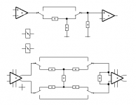
Using an inverting stage, you could make a mix-amp. Each input has a different gain weighting, and by choosing the resistor values carefully, you can make them dB's in powers of two, as shown. This isn't too difficult in practice...
Then, addres the relays using normal binary... It's a crazy plan, but it might work
Attachments
Relay etc
Mark,
Thanks. You know of course that there are modern switches with <5 Ohms Ron with very flat resistance. They would be OK used in a virtual ground mode.
You last scheme might work, but note that in the -64dB pos the resistance ratios around the opamp are > 1: 1000. Not easy, you know, noise and all that. An R/2R ladder (available as SIPs from Vishay) with a couple of the above mentioned switched could do the trick.
Jan Didden
Hi Jan,
")
But the steps would be linear!An R/2R ladder (available as SIPs from Vishay) with a couple of the above mentioned switched could do the trick.
sonnya's method is one possible solution, and quite an elegant one at that.
The other soution is not bothering at all about logarithmic behaviour. While I admit that there are situations where it is important to have logarithmic readout, it definitely isn't, at least not to me, for the volume setting of an amp.
I usually set the volume so that it is pleasing to my EARs and not to make any kind of readout pleasing to my eyes.
Regards
Charles
relay etc
Right. AD had some MDACs that were really 17-bit R/2R ladder DACs with internal conversion through a look-up table so the input dig code would be in equal steps of I believe .375dB for 70dB range. AD7745 or something. Discontinued a couple of years ago because you guys insisted on buying stepper switches ...
Jan Didden
sonnya said:It would require a lookup table in a micro to make them log.
Right. AD had some MDACs that were really 17-bit R/2R ladder DACs with internal conversion through a look-up table so the input dig code would be in equal steps of I believe .375dB for 70dB range. AD7745 or something. Discontinued a couple of years ago because you guys insisted on buying stepper switches ...
Jan Didden
Hi,
Made a preamp (tube one) with:
- PIC 16F84 controller is in sleepmode when no code is received.
- I2C IO expanders used to control the relays for switching the inputs, volume and power of the preamp.
- Bourns position decoder (ACE-128) on the volume, so it's position is know at all times.
- The conversion table for the position decoder is stored in an I2C EEprom. (24C02)
- The PIC can be programmed in-circuit, a DB9 connector at the back of the preamp can be connected to a serial port.
- Controls my Kenwood tuner using the Kenwood 8-bit XS protocol (on/off, change presets)
Using shunt-volume regulation at the moment with Alps pot.
My relais look like the pass X1 relays used for input selection...!
I am using SDS relays (filled with some gas, sliding contacts if i remember correctly)
Anyway, If you need some routines for the pic (the 16f84 is much smaller!!), let me know.
Click on my www below for more info. Don't use a display on purpose. Displays have their own controller, clock, noise...
Relays are driven with ULN2004, Alps and one relay with TC4469.
IO expanders are 8-bit PCF8574. If you need more info on this, let me know aswell.
All is working very well, no problems so far (two of these controllerboards are in use).
Greetings,
Guido
I took a bit longer than expected.
There is an unbalanced and a balanced one. Each only have 1 stage, but you can add as much as you like (well, a 120dB attenuator may not be useful). I put in a L-type attenuator, but you an as well use T, pi or bridged T (like already showed in a post here) for the unbalanced. The balanced is a H-type, but O works just as well. Formulas for all those can be found on the web or in HF textbooks.
The resistor at the output buffer is needed only once, but is needed. This is the impedance you design for.
The one I made is of the L type with 6 stages. Impedance 1k and steered by a simple up/down counter.
Attachments
I thought i might drag this thread up again, it has gone a bit quite.......
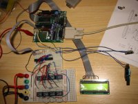
Yesterday i had a day to spare so, i thought i might have a go at making one of these attenuators ala unblanced part of pass pre-amp p1.7 (i think, u know the one with the 8 relays and res from 8k to 60ohm) (also i hadn't read this thread up to this point). So i grabbed some relays from the local shop and fired up my Elecktor 8052 flash project board and shuved in some code. I finally finished wiring up the bread board (prototype board) and got it working. Input to the relays was just BCD with 00 being all relays off and FF being all on.
I connected a 12 v DC input and put my multimeter and saw the output going up and down nice with clicked precision. However, that is when it struck me.. it's linear, i need log. So i connected up to a channel of my set-up anyway and gave it a proper test, it sounds good. But it's linear track is totally wrong, it doesn't have a fine enough adjustment for the 'quiet' end for night time listening and much too fine adjustment for the 'loud' end.
So i searched DIYaudio to see what i could find.. much the same here somebody suggested using a log lookup table, but that won't give me a finer adjustment, i could use -10db to -60db attenuators at the input then a buffer then -1db to -9db attenuators then another buffer which is a very good solution but u need too stages of amplification which i dont want (i wanna keep this project descrete SE) . Today i have been tumbling ideas around in my head all day . The best i can come up with is.....
Coupling a small stepper motor to a 10 turn or 22 turn cermet track trimmer or pot then getting some uControl to give me steps of adjustment. So with a 22 turn trimmer i should get over 1000 diffrent settings. Or i could use a 10 turn log pot, people say with dual log pots that they 'don't track well' does this apply with 10 turn cemets ones say 2 seprate ones driven by steppers?
With over 1000 settings on a linear track i could then use a look up table i guess with fine enough adjustment on the 'quiet' end of the track (a few steps of the stepper) and the loud end the uControl will have to turn a bit more. Also a 'calibration' or setup run will be ness. so that the uControl can find where it is on the volume control (i.e wind all the way to quiet and then start taking it steps from there) but this won't be difficault i think i could nail that problem.
tho. when i think i could have a pre-amp with internal steppers and trimmers i think i have been having one too many coffees!!
ANY COMMENTS?
p.s this is what my set-up yesterday looked like
p.s.s whats the news on brian and jordan's project?
Yesterday i had a day to spare so, i thought i might have a go at making one of these attenuators ala unblanced part of pass pre-amp p1.7 (i think, u know the one with the 8 relays and res from 8k to 60ohm) (also i hadn't read this thread up to this point). So i grabbed some relays from the local shop and fired up my Elecktor 8052 flash project board and shuved in some code. I finally finished wiring up the bread board (prototype board) and got it working. Input to the relays was just BCD with 00 being all relays off and FF being all on.
I connected a 12 v DC input and put my multimeter and saw the output going up and down nice with clicked precision. However, that is when it struck me.. it's linear, i need log
. So i connected up to a channel of my set-up anyway and gave it a proper test, it sounds good. But it's linear track is totally wrong, it doesn't have a fine enough adjustment for the 'quiet' end for night time listening and much too fine adjustment for the 'loud' end. So i searched DIYaudio to see what i could find.. much the same here somebody suggested using a log lookup table, but that won't give me a finer adjustment, i could use -10db to -60db attenuators at the input then a buffer then -1db to -9db attenuators then another buffer which is a very good solution but u need too stages of amplification which i dont want (i wanna keep this project descrete SE) . Today i have been tumbling ideas around in my head all day
. The best i can come up with is.....Coupling a small stepper motor to a 10 turn or 22 turn cermet track trimmer or pot then getting some uControl to give me steps of adjustment. So with a 22 turn trimmer i should get over 1000 diffrent settings. Or i could use a 10 turn log pot, people say with dual log pots that they 'don't track well' does this apply with 10 turn cemets ones say 2 seprate ones driven by steppers?
With over 1000 settings on a linear track i could then use a look up table i guess with fine enough adjustment on the 'quiet' end of the track (a few steps of the stepper) and the loud end the uControl will have to turn a bit more. Also a 'calibration' or setup run will be ness. so that the uControl can find where it is on the volume control (i.e wind all the way to quiet and then start taking it steps from there) but this won't be difficault i think i could nail that problem.
tho. when i think i could have a pre-amp with internal steppers and trimmers i think i have been having one too many coffees!!
ANY COMMENTS?
p.s this is what my set-up yesterday looked like
p.s.s whats the news on brian and jordan's project?
Attachments
The aleph P volume control is only linear if you use all the binary values between 0 and FF.. The way I'd do it (and the way Pass does it), is to choose the steps that yeild the desired response.Helix said:ANY COMMENTS?
However, the Aleph P only gives you to -48db.. I've posted a graph of the attenuation vs steps.. Its alright, but I like ftorres's design better.. You can find it here. Its got better range and precision.
As for the status of the project? Nothing much done in awhile.. I got a bit side-tracked when my father offered to bank-roll a speaker/amplifier project for him (gainclone/w3-871s goodness). For me, the next step is to prototype ftorres's attenuator. I also found a motorized pot that I really like.. Page 2, the "Dual 10k linear taper". I just need to brush up on controlling a dc motor (h-bridge?). Oh yeah, and I got my I2C parts form Philips.. PCA9555 is my part of choice..
--Jordan
Attachments
Helix:
Hmm... trimmer pots will wear out real fast. They're really only designed for a few operations to set come circuit parameter, and then maybe a circuit calibration a handful of times over the life of the device... constant twiddling with stepper motors would probably wear them out right away. A better option is probably just to use ganged, motorized audio potentiometers. If you can find the type which plug together, you could put a linear taper pot as the last one. Feed that linear pot a constant DC voltage, then A/D it's output to give you precise measurement of the angular position. A little control algorithm in a uC, and you can get that motorized pot to sit right where you want it. With a 10-bit A/D, you would have pretty fine control over the motor position.
Hmm... trimmer pots will wear out real fast. They're really only designed for a few operations to set come circuit parameter, and then maybe a circuit calibration a handful of times over the life of the device... constant twiddling with stepper motors would probably wear them out right away. A better option is probably just to use ganged, motorized audio potentiometers. If you can find the type which plug together, you could put a linear taper pot as the last one. Feed that linear pot a constant DC voltage, then A/D it's output to give you precise measurement of the angular position. A little control algorithm in a uC, and you can get that motorized pot to sit right where you want it. With a 10-bit A/D, you would have pretty fine control over the motor position.
update
Hrm, haven't been here in awhile. So many projects, so little time.
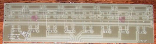
Anyhow, I just got my volume boards made.. They implement the Aleph P 1.7 attenuation scheme. The idea was to have as much flexibility as possible.. The 8-pin dip header will go to the driver/control circuitry, which will be comfortabily shielded from the attenuation board.
Remember, this is just a prototype, so I didn't put much time into the layout.. I may re-work the board and get it professionally milled later.. Also, the relay footprint I chose wasn't necessarily the best choice, but rather one that accommodated the relays I have lying around.
Any comments, suggetions?
--Jordan
Hrm, haven't been here in awhile. So many projects, so little time.
Anyhow, I just got my volume boards made.. They implement the Aleph P 1.7 attenuation scheme. The idea was to have as much flexibility as possible.. The 8-pin dip header will go to the driver/control circuitry, which will be comfortabily shielded from the attenuation board.
Remember, this is just a prototype, so I didn't put much time into the layout.. I may re-work the board and get it professionally milled later.. Also, the relay footprint I chose wasn't necessarily the best choice, but rather one that accommodated the relays I have lying around.
Any comments, suggetions?
--Jordan
Attachments
Crazy idea
How about a constant impedence remote controlled attenuator.
Basically, switch in a pair of voltage divider resistors using 24 DPST relays. Pick resistors based on constant impedence R1 + R2 and dB at each step.
Overkill, but signal only goes through one resistor and we can maintain impedence. Could also be used to switch the outputs of a transformer based attenuator S&B TX-102.
I am in the process of designing this beast.
Dale
Re: Crazy idea
Granted, the steps aren't perfectly logarithmic, but you can choose approximately logarithmic steps if you like..
--Jordan
Since the resistors are either between the output and input, or output and ground, and all in parallel, then the total impedance should remain constant, right?harvardian said:How about a constant impedence remote controlled attenuator.
Basically, switch in a pair of voltage divider resistors using 24 DPST relays. Pick resistors based on constant impedence R1 + R2 and dB at each step.
Overkill, but signal only goes through one resistor and we can maintain impedence. Could also be used to switch the outputs of a transformer based attenuator S&B TX-102.
I am in the process of designing this beast.
Dale
Granted, the steps aren't perfectly logarithmic, but you can choose approximately logarithmic steps if you like..
--Jordan
jgwinner said:won't the relays BRIEFLY present an open circuit though?
no u just make it make befour break (MBB)
This scheme should work fine. Only problem is it uses 24 relays and only gives you 25 steps of attenuation
- Status
- This old topic is closed. If you want to reopen this topic, contact a moderator using the "Report Post" button.
- Home
- General Interest
- Everything Else
- Relay-based passive volume control project