I have done some research into the vfds, here is the pricing direct from Noritake:
Noritake 7000 series
http://www.noritake-elec.com/7000.htm
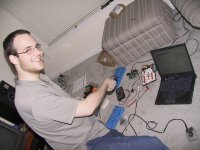
GU140X32F-7002 (one in my picture above, beautiful display)
1-9 $96
10-49 $88.80
50-99 $72.10
100-199 $54.80
GU140X16J-7002 (half the height of the above vfd)
1-9 $61.80
10-49 $57.20
50-99 $46.40
100-199 $35.20
GU280X16G-7002 (twice the width of the above vfd)
$96.90
$89.60
$72.70
$55.20
In terms of rotaty encoders, I am thinking of using a Greyhill 32 position with pushbutton:
grayhill pn: 62A11-01-050S
digikey pn: GH3048-ND
Datasheet: http://38.254.60.87/embrace/IMAGES/PDF/bltn725.pdf
Would anyone be interested in putting together a group buy of vfds for a project like this?
--
Brian
Noritake 7000 series
http://www.noritake-elec.com/7000.htm
GU140X32F-7002 (one in my picture above, beautiful display)
1-9 $96
10-49 $88.80
50-99 $72.10
100-199 $54.80
GU140X16J-7002 (half the height of the above vfd)
1-9 $61.80
10-49 $57.20
50-99 $46.40
100-199 $35.20
GU280X16G-7002 (twice the width of the above vfd)
$96.90
$89.60
$72.70
$55.20
In terms of rotaty encoders, I am thinking of using a Greyhill 32 position with pushbutton:
grayhill pn: 62A11-01-050S
digikey pn: GH3048-ND
Datasheet: http://38.254.60.87/embrace/IMAGES/PDF/bltn725.pdf
Would anyone be interested in putting together a group buy of vfds for a project like this?
--
Brian
Brian says this display is super cool. Since he has seen it and worked with it I think we should definately get one of the versions of it.
The fact that it can display mutiple data in separate frames sounds perfect for our needs. It is likely we will often want to display different text at he same time. Maybe the text gets big while adjusting a function, then recedes to a small window after.
OK there are a million options. In fact I can see Brian or others releasing later versions of the PIC with more and more groovy features. In fact I need that temp function to monitor how much I can turn up the variac on my Son o Zen. Maybe the choice of the size he shows or half size should wait to see the number orderd. If a large quantity is ordered the bigger display is reallly not that much more.
There is an amazing price break at 100 units, and I think we might get that many orders. The biggest problem is the logistics I think. That would be 1800 relays for instance. Someone would certainly have to help Brian finance the thing, unless he decides to go into business. Imagine the great price we would get on almost 2000 relays!!
If the basic 2 channel w/ display setup has all the features Brian mentioned above, plus as many more as the human brain can devise, then it would be a screaming bargain at $150. (just a guess at the 100 order price). Still, we're talkin' $15000 dollars here- how can this be done?
I'm definetly in for a stereo version!
Hey, so I'm glad to see such enthusiasm in this project. I’m Brian’s roommate btw.
Anyhow, I was wondering about the resistor-relay network. When I made my initial circuit, I used a handful of the resistor values from the volume circuit in the Aleph P. However, Craig made the point that specifying the resistor network was a tricky task; never mind deciding on how to trigger the relays. Should we be attempting to specify a newer, more precise resistor network, or would it be sufficient to use the Aleph P version? I suppose we could use more than 8 relays per balanced channel; however I’m not really sure how to approach designing a new resistor network. Anyone have any ideas where I might to go to read up on the subject? Also, how is the tradeoff between the size and cost of the relays vs. the precision that can be obtained? For instance, it would certainly be nice to have .5dB steps from -70 to 0, but I don’t know how realistic it would be.
Any insight would be appreciated.
Thanks
--Jordan
JordanG said:Hey, so I'm glad to see such enthusiasm in this project. I’m Brian’s roommate btw.
Indeed, this is the guy that makes it all happen.
--
Brian
Attachments
Hey Jordan,
Brian is almost a folk hero around here. If you pull this off you will be a folk LEGEND! I guess the resistor conundrum can be worked on while you design all the other factors?
Obviously we need to decide these issues before the board layout is designed:
how many relays? Can one or two more give precise 1 db increments? Do we really care?
Is the shunt design really better? if so, how is it implemented?
Later on we can figure out how to deal with the huge cost of this.
At the minimum Brian would need to supply the pic and PCB.
Variac said:
Is the shunt design really better? if so, how is it implemented?
Later on we can figure out how to deal with the huge cost of this.
At the minimum Brian would need to supply the pic and PCB.
Shunt design? Could you point me in the direction of such a design, as I'm not familiar with it. Truth be told, I'm a humble computer engineer.. Almost no analog knowledge whatsoever (that's what Brian's for).
And speaking of what is to be supplied, I'd like to say that the design I'm working out with Brian is starting to look pretty nice. I'm envisioning a control board with a microcontroller at its heart (most likely a PIC18 series). The board would initially require that nifty Noritake display (gotta start somewhere), though I've been considering lower cost displays after we get the intial design down. The passive volume circuit boards would each support 2 balanced channels, and up to 5 boards could be tied to the control logic (for up to 10 channels of balanced audio per control board). The control circuit will be setup to "sense" the presence of additional volume boards, so you're in no way tied down to 2 channels if that's what you start with. The "sensing" feature can be added at almost no additional cost to the end user, as it is a function of the control circuitry that I've chosen to use (I2C). A learning remote feature is also forthcoming, so that the user could use any decently modern IR remote. Also, the PIC18 has an EEPROM on it, allowing allowing us to do things like setting the left and right channels, naming different channels, saving balance settings, brightness settings, etc.
Of course, anything can change at this point, that's just the current status.
--Jordan
USB boot loader
Hi Jordan, Brian,
A friend and I are working on a PIC18 project in which one of the boards is a USB-CAN converter. We wrote a USB bootloader. The code downloads in a couple of seconds. We also have a board that does a servo/stepper with a CAN interface. We also have a bootloader for the CAN board in which we send the code from the PC to the USB board and then on to the CAN based board. For a 28K program (almost 80% of 18F458), the sownload takes only 6 seconds.
Dale
P.S. I am using the CCS C compiler. A lot easier than assembly.
Hi Jordan,JordanG said:
Shunt design? Could you point me in the direction of such a design, as I'm not familiar with it. Truth be told, I'm a humble computer engineer.. Almost no analog knowledge whatsoever (that's what Brian's for).
Take a look at this thread started by HH/Fred Dieckmann (Brian can fill you in on that story). He presents a passive shunt-type volume control with no resistors in the signal path. It truly is a minimalist approach. He uses a pot for his circuit but that can just as easily be discrete steps.
http://www.diyaudio.com/forums/showthread.php?s=&threadid=2608&highlight=passive+volume+shunt
Brian,
I know that Dorkus mentioned this on page one of this thread. Sorry to be a pest, but have you considered the shunt approach?
Rodd Yamashita
I guess I am a regular customer now as I bought Brian's really nice Aleph boards. I would be interested in this project. I was thinking about volume and selector controls for XBOZ . And I do not know if it would work well but as a passive control in an AlephX intergrated.
It is not clear to me how many single ended and balanced inputs and outputs will be available.
I am interested in one pair of balanced inputs. For a DAC. Is this planned?
It is not clear to me how many single ended and balanced inputs and outputs will be available.
I am interested in one pair of balanced inputs. For a DAC. Is this planned?
roddyama said:
Brian,
I know that Dorkus mentioned this on page one of this thread. Sorry to be a pest, but have you considered the shunt approach?
Rodd Yamashita
Well, you have to start somewhere, so the current plan for Jordan and I is to get prototype pcbs done for the 8 relays and see how it works out. While the boards are getting made, we will also work on designing some other boards based on a different methodology, such as a shunt volume control. I want to try the P1.7 version out first and see how it actually works in practice, the built something else to compare it to.
--
Brian
Re: USB boot loader
Dale,
That sounds like quite an interesting and complex project. Do you have any sort of webpage with more details on this? Jordan has tried the CCS C compiler, but said that it made timing issues with stuff like IR communication more difficult, due to the stack management.
What parts do you use for the above mentioned project?
--
Brian
harvardian said:Hi Jordan, Brian,
A friend and I are working on a PIC18 project in which one of the boards is a USB-CAN converter. We wrote a USB bootloader. The code downloads in a couple of seconds. We also have a board that does a servo/stepper with a CAN interface. We also have a bootloader for the CAN board in which we send the code from the PC to the USB board and then on to the CAN based board. For a 28K program (almost 80% of 18F458), the sownload takes only 6 seconds.
Dale
P.S. I am using the CCS C compiler. A lot easier than assembly.
Dale,
That sounds like quite an interesting and complex project. Do you have any sort of webpage with more details on this? Jordan has tried the CCS C compiler, but said that it made timing issues with stuff like IR communication more difficult, due to the stack management.
What parts do you use for the above mentioned project?
--
Brian
gnomus said:I guess I am a regular customer now as I bought Brian's really nice Aleph boards. I would be interested in this project. I was thinking about volume and selector controls for XBOZ . And I do not know if it would work well but as a passive control in an AlephX intergrated.
It is not clear to me how many single ended and balanced inputs and outputs will be available.
I am interested in one pair of balanced inputs. For a DAC. Is this planned?
The design will be modular, so there will be one control board, one volume control board for each 2 balanced channels, and there is a possibility of an input relay selection board also.
For now, we are just working out a two board solution with one control board, and one volume control board. Jordan's post above explains this a bit better.
My plan for this is to use it attached to the balanced output of my bosoz, then going into my aleph-x. This is my plans for it, but it can be used many other ways. You could even run 4 unbalanced channels through one 2 channel balanced board if you wanted. I am going to use another board to run between my unbalanced cd player and my amplifier also.
--
Brian
Oops...
There was an error in the program I wrote to graph the attenuation vs. step, so please ignore that graph and the conclusions I derived from it!
The attenuation is a linear function of step, similar to a linear potentiometer. In order for the function to be smooth, each resistor must be twice the resistance of the previous, and the P1.7 design is close to this. Of course, what we actually want is a logarithmic response, so this isn't ideal. What this design does give us is a minimum of relays.
We could add a fixed shunt resistor, as in Rod Elliot's notes here:
http://sound.westhost.com/project01.htm
This would make the response closer to logarithmic.
Using 10 relays provides up to 60dB of attenuation, which some people might like. I personally think 48dB with 8 relays isn't enough.
Craig
Brian/Jordan,
I was wondering if the systems that you guys are designing would solve the problem of turn on/off thumb from the BOSOZ. (See this thread for some of the ways that I have already tried http://www.diyaudio.com/forums/show...=15&highlight=speaker protection&pagenumber=7)
From what I have read so far on this thread, it appears that the relays should be able to short out the output at turn on/off to supress the turn on/off transient. I would like to know if you guys can implement this into the design if you have not considered this option yet.
Sorry to fall in late, but I have been away for a couple of days.
Why not a constant impedance attenuator? I made one (stereo) with 6 relays in each side. With a 1dB step you get 63dB max attenuation and a nice log law. You can make these balanced or not, it only determines the relay you need. Mine has a 1k impedance, but you can go for whatever you want.
Why not a constant impedance attenuator? I made one (stereo) with 6 relays in each side. With a 1dB step you get 63dB max attenuation and a nice log law. You can make these balanced or not, it only determines the relay you need. Mine has a 1k impedance, but you can go for whatever you want.
Havoc,
")
Rodd Yamashita
"Me" too.Variac said:Havoc:
do you have a reference or scematic of this for the ignorant (me)among us ?
Rodd Yamashita
Havoc said:Sorry to fall in late, but I have been away for a couple of days.
Why not a constant impedance attenuator? I made one (stereo) with 6 relays in each side. With a 1dB step you get 63dB max attenuation and a nice log law. You can make these balanced or not, it only determines the relay you need. Mine has a 1k impedance, but you can go for whatever you want.
I am interested to see what you are talking about, can you post a schematic, or guide me to somewhere where I can learn about this?
--
Brian
- Status
- This old topic is closed. If you want to reopen this topic, contact a moderator using the "Report Post" button.
- Home
- General Interest
- Everything Else
- Relay-based passive volume control project