I just had an interesting idea. I believe that if you connect the bases of two complementary transistors then a small change in current in the first transistor would create a change in voltage in the complementary transistor while not deteriorating the original current and with it being very linear if the transistors are complementary enough (e.g. 2N3904 and 2N3906). I believe that this could be used as maybe a biasing scheme. I haven't really thought much about this so deal soft blows, ok? 
 . Here it is:
. Here it is:Attachments
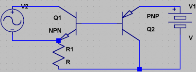
I am using a simulator . in it I am using a .01V 1kHz sine as the input and the transistors are 2N3904/2N3906. The supply is 1v
and it currently looks more like an amplifier. biasing? I am not too good at biasing yet... I thought that a little more biasing might be needed... are you talking about putting a resistor hanging or balancing on the base connections? I think that this would destroy the linearity of the circuit. But putting one between the bases would work if that was the place. Are you talking about balancing a resistor on the collector of Q1? I think that this would work. You might have to be more specific on the biasing part because I am not quite sure about biasing yet. I recognize that "Q1 would just be a diode" means that something doesn't have current running through it like it should. Cheers to not saying "it won't work".
. in it I am using a .01V 1kHz sine as the input and the transistors are 2N3904/2N3906. The supply is 1vand it currently looks more like an amplifier. biasing? I am not too good at biasing yet... I thought that a little more biasing might be needed... are you talking about putting a resistor hanging or balancing on the base connections? I think that this would destroy the linearity of the circuit. But putting one between the bases would work if that was the place. Are you talking about balancing a resistor on the collector of Q1? I think that this would work. You might have to be more specific on the biasing part because I am not quite sure about biasing yet. I recognize that "Q1 would just be a diode" means that something doesn't have current running through it like it should. Cheers to not saying "it won't work".
Hi keantoken,
I am no expert. Especially with simulators!
0.01V is too small to cause a junction to conduct. But the colector of Q1 should have a positive supply and an AC path to your circuit common (whatever you choose that to be). Your signal source has no return with regard to the rest of the circuit, it's floating.
Could you please indicate where you are taking your amplified signal from?
-Chris
I am no expert. Especially with simulators!
0.01V is too small to cause a junction to conduct. But the colector of Q1 should have a positive supply and an AC path to your circuit common (whatever you choose that to be). Your signal source has no return with regard to the rest of the circuit, it's floating.
Could you please indicate where you are taking your amplified signal from?
Well, I've drawn some silly things in the past. Glass houses.Cheers to not saying "it won't work".
-Chris
The light went on... maybe.
... I didn't think about this one... in order for .01V to alter a junction, there must already be a somewhat sufficient voltage running through it, so I suppose connecting a resistor between positive supply and Q1's collector would be essential. Sorry, I didn't understand what you meant by "where are you getting your output from" in your last post, I thought you meant what the input I was using was. I am getting this from the emmitter current on Q2. Thanks!
... I didn't think about this one... in order for .01V to alter a junction, there must already be a somewhat sufficient voltage running through it, so I suppose connecting a resistor between positive supply and Q1's collector would be essential. Sorry, I didn't understand what you meant by "where are you getting your output from" in your last post, I thought you meant what the input I was using was. I am getting this from the emmitter current on Q2. Thanks!
Ok, bump that supply up to 2V. I think Q1 might not be getting enough base voltage. Hmmm, This could be tricky (for me). If the input voltage is high enough, then it may start reverse-biasing Q1. I would have to make sure there was enough voltage running through Q1 as to counteract this without disrupting the linearity of the circuit.
... I suppose high impedance is best for small-signal work, right? I have been noticing a very profound lack of suggestions, like, none. how could I get a high-impedance input without disrupting linearity? I believe someone's expertise other than mine would be very helpful.
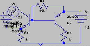
Also, changing both R1 and R2 to 150k works better. I think I'll try the low impedance input method and see what I can do with that.
Also, changing both R1 and R2 to 150k works better. I think I'll try the low impedance input method and see what I can do with that.
Hi keantoken,
Firstly, you are using the least sensitive terminal of the transistor. The base would be the expected place to inject a signal. Your gain would be the highest there. The emitter is another good place to inject a signal as long as it's a low impedance one.
Keep plugging away at different solutions.
-Chris
Is it allowed for anyone else to butt in on this thread?
First off, although simulators may show PNP and NPN transistors as being very similar, they aren't. I have a curve tracer and have investigated notionally complementary pairs. In general, NPN transistors show less Early effect than PNP. There also tends to be a slight difference in the output characteristics at low voltages. Your scheme also appears to rely on the current gain of each device (a notoriously unstable parameter). I think you need to find out a little more about the fundamentals of how practical transistors are used and their limitations compared to theoretical transistors. Have a bit of a think, then come back...
First off, although simulators may show PNP and NPN transistors as being very similar, they aren't. I have a curve tracer and have investigated notionally complementary pairs. In general, NPN transistors show less Early effect than PNP. There also tends to be a slight difference in the output characteristics at low voltages. Your scheme also appears to rely on the current gain of each device (a notoriously unstable parameter). I think you need to find out a little more about the fundamentals of how practical transistors are used and their limitations compared to theoretical transistors. Have a bit of a think, then come back...
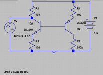
I don't want to put an input at the base because the pure base coupling is what makes the circuit linear. I am trying the emitter-input method and there is only slight distortion when R1 and R2 are 300k and R3 and R4 are 10k. I am trying to increase the voltage in the output with as little distortion as possible. Yes, anyone who wants to post in this thread can, and I encourage them to!
Hi EC8010,
The cat is always welcome! I can't help but notice there are no mice around!
Half the fun of electronics is discovering things for yourself. Keantoken, Your circuit is so simple, why not build it? If you get it working, build another and play music through them.
-Chris
The cat is always welcome! I can't help but notice there are no mice around!
Half the fun of electronics is discovering things for yourself. Keantoken, Your circuit is so simple, why not build it? If you get it working, build another and play music through them.
-Chris
hmm, I'll see if I can get around to that. I want to make sure that it won't blow anything out first, though. I also need to find out a way to make an output. Electronics is wierd... I was working on this circuit and it somehow evolved into a power supply idea  . I will try to optimize it some more and when I think I have found a useful application or something I'll post again.
. I will try to optimize it some more and when I think I have found a useful application or something I'll post again.Hi keantoken,
A power supply regulator is an amplifier. The only difference is that you want it to stay still.
-Chris
That's normal for me and others I'm sure. In the corporate world they call that cross pollination - except it all happens in your own mind.Electronics is wierd... I was working on this circuit and it somehow evolved into a power supply idea
A power supply regulator is an amplifier. The only difference is that you want it to stay still.
-Chris
- Status
- This old topic is closed. If you want to reopen this topic, contact a moderator using the "Report Post" button.
- Home
- General Interest
- Everything Else
- Strange idea that wasn't much but I decided to ask anyways.