I have a Yamaha "Natural Sound" CT-610 tuner. It is an analog unit from the 70s. I was doing a cleanup on it when I noticed that there is a resistor (measures about 2.2 meg) going from a line voltage wire to the chassis. The power plug is non-polarized 2 wire, typical from that era. The power switch switches the transformer secondary... The transformer is always energized.
Being an Electrician (but not an electronics technician), I chopped off the cord cap and replaced it with a 2-wire polarized plug, making the wire with the resistor attached always plugged into the building neutral (which is always grounded).
My questions.. Why bother putting in this resistor at all?
Why switch the xfrmr secondary and not the primary?
The Yamaha engineers must have had a reason.. but what? Maybe because this was high end gear, it was more to do with niggly stuff.
Back in the '70s, three wire plugs were not very common. Today they are and they're MUCH safer- and unless the tuner has a double-insulated case, they're required (as an electrician, you're probably more familiar with this than most).
I'd update it to current standards. That means three wire cord, green wire FIRMLY attached to chassis, and the transformer primary totally isolated from ground.
And keep the 2.2M in a box somewhere as a souvenir. BTW, what did it look like? It's possible that it was an MOV or something like that.
I'd update it to current standards. That means three wire cord, green wire FIRMLY attached to chassis, and the transformer primary totally isolated from ground.
And keep the 2.2M in a box somewhere as a souvenir. BTW, what did it look like? It's possible that it was an MOV or something like that.
Hi cpemma and SY.
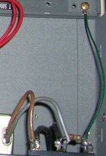
Here is a pic. There are more pics, including inside shots of newer models at
http://audiokarma.org/forums/showthread.php?t=75738
I'm not sure if non-members can see the pics though...?
The newer models have a resistor and an mov (or a cap- I can't tell) connected to the chassis, the older "non II" models just have a resistor. I was worried that in a catastrophic situation, the chassis could become highly en-live-enated and en-jigglefy anyone that touches it.
Attachments
I'm not an electronics tech, so my worry with adding a ground wire would be ground loops. Not even new equipment has 3 wire cords... they just use standard polarized 2 wire cords like incandescant lamps. (In the old days, you could get a shock just changing a lamp's bulb if the screw shell was hot. You could plug it in any old way. There was no upside-down). I guess the new equipment is electrically isolated from the mains. To me, the wonderment comes from the fact that tuners aren't like tape players... They need antennas. That involves grounding. My head is spinning. javascript:smilie(' ')
')
xeye
')xeye
my understanding of that 2.2 MegOhm resistor is to supply a discharge path if the chassis voltage floats above the line voltage due to static buildup and what-not. If there is no other leakage path from your perhaps floating chassis, there is a danger that static electricity could arc through the varnish on your transformer windings. The 2.2 Meg resistor bleeds these currents off to the AC grid. If you decide to wear rubber shoes and comb your hair, then touch the volume knob your generated static will be bled through the resistor and not through a hole punctured in the transformer winding varnish. ...at least that is my understanding.
New equipment with two wire power cords will be double insulated. Your chassis is not! Metal chasses will always be grounded and used with three wire cords.
Ground loops are a separate issue; the three wire system just provides a safety ground. Your signal ground can be tied to the chassis ground at one point. If ground loops develop, the signal ground can be lifted from the safety ground via a small (20 ohm) resistor to break up the loop. Do NOT lift the safety ground under any circumstances.
Ground loops are a separate issue; the three wire system just provides a safety ground. Your signal ground can be tied to the chassis ground at one point. If ground loops develop, the signal ground can be lifted from the safety ground via a small (20 ohm) resistor to break up the loop. Do NOT lift the safety ground under any circumstances.
"...why switch the secondary and not the primary?". That's a quizzler. . I don't think it would have been a question of money. A difference in switch contact rating for current and flashover shouldn't be an issue. They were already switching the primary's on their receivers. Maybe they couldn't get in under the wire for UL or CSA certification?? Perhaps it reduced certification headache to just hardwire all of the line side and switch the isolated side? I think putting on the polarized plug with the resistor always on the neutral side is not a bad idea. You'll measure less chassis to earth voltage than you would get if the plug was flipped (assuming the resistor is the dominant leakage path). I don't think there would be any impact on any "ground loop" related issues, but your fingertips would know the difference if you were grounded and lightly touching the chassis.
AndrewT said:Hi,
I am real glad I live in the UK.

You surely remember our 2-pin sockets?

mrshow4u said:"...why switch the secondary and not the primary?".
<snip>
I don't think there would be any impact on any "ground loop" related issues, but your fingertips would know the difference if you were grounded and lightly touching the chassis.
I think it may have something to do with static as Mrshow4u said. There is a connector on the back for coax cable, the shield connects to chassis ground. I'm just imagining various situations with antennea from the 70s fluttering in the wind, pointing to lightning with it's come-hither little fingers
I didn't realize that a ground loop could be broken with a mere 20 ohm resistor.
There was a lightning storm here last night. The grounding system in this house sucks. I think I'll just sell the tuner on Craigslist.
PS- This is a pretty cool site.
AndrewT said:Did we have 2 pin sockets in the UK after WW2?
I can recall the 13A rect pin, 15A round pin, 5A round pin. But that's my limit.
My parents' house was built immediately after the war and had some 2-pin 5A sockets mounted on the skirting board when we moved in, along with 15A 3-pin to run an electric fire. Not many, it was common practice then to run the hoover upstairs via a 2-pin to bayonet adaptor from a ceiling light fitting.
The 13A system came in in 1947 but I guess took a few years to reach Yorkshire, plus it involved running a ring main rather than just another spur or swapping the socket.
RS still stock the 5A & 15A 3-pins.
Hi Cpemma,
thanks for that link, I'll go back and read it properly.
Mullins talks about BS546, the predecessor to BS1363 flat pin plug & sockets.
BS546 seems to have been the standard upto and through WW2 but he makes no mention of 2pin sockets.
I wonder if the sockets, you mentioned, were old stock and all that was available due to the war effort?
Makes me wonder just how old those 2pin sockets were and what plugs were available to fit them?
Do not confuse a 2pole +earth system for 2pin.
AndrewT said:Makes me wonder just how old those 2pin sockets were and what plugs were available to fit them?
From Wikipedia
5A 2 pin
This plug is what became the UK standard shaver plug and is similar but slightly larger than the Europlug. British shaver sockets and adaptors tend to be sized to accept this, Europlugs and two pin American and Australian plugs.
I remember a plastic hemispherical body, the back screwed off, the flex went through a polar hole and was attached to the pins. Much like a current bulb holder. Pins were split to provide a better grip in the socket.
Is this really true??? No 2-pin sockets?? I certify a lot of equipment from Korea and Japan and most if not all comes with two pin plugs. I guess I should say that current electrical code for receptacles/sockets here is 3-wire grounded or GFI for kitchens and bathrooms. Many older houses still have 2-pin receptacles. Many if not most consumer electronics come with 2-wire plugs, however.
- Status
- This old topic is closed. If you want to reopen this topic, contact a moderator using the "Report Post" button.
- Home
- General Interest
- Everything Else
- Why this resistor?