Hi all,
I was excited to find that there was a LM2917 based rev-counter thread right under my nose at DIYaudio in some of my searching for answers over the last few days. I've posted in the same sub-forum as I've assumed it's the right place.
I've stuck an issue in that my old current sensing Smiths RVI (from the late 60's early 70's) meter does not work with an electronic ignition, and there exist very few DIY circuits out there that might drive this meter with it's relatively low impedance.
It seems to be a ammeter style movement which would be fine with the LM2917, except that the movement of meter I have measures 13ohms resistance and responds to 10mA every 1000rpm. This is a problem at the LM2917's max is 50mA, and I would really like to be able to measure up to 6500rpm ( yes my engine has been breathed on and is balanced so it's not an issue") ).
).
The part inside the LM2917 that sets the V/current is an op-amp, so I thought I might strap a small signal transistor capable of a few hundred mA inside the feedback loop of the op-amp and hopefully it would allow me to sink the current for the meter through that. My guess is that it would work for voltage, current I'm not so sure about however.
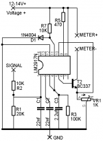
You can find the LM2917 info page on NatSemi's site as well as a schematic that shows the innards of the LM2917. Page 10 of the LM2917 datasheet shows the schematic that is the basis of my circuit - mine has 100k on pin3/pin4 for 4 cylinders, and a larger cap to stop the needle swaying.
Pin8 is the one I'm not sure about. Should it be connected to 12-14v+, the meter movement still or via that 470ohm resistor to stop any issues.
I've attached my circuit diagram from Eagle as an image - please feel free to make any ammendments and direct me to any electronic theory I'm not grasping
Cheers,
raro'
I was excited to find that there was a LM2917 based rev-counter thread right under my nose at DIYaudio in some of my searching for answers over the last few days. I've posted in the same sub-forum as I've assumed it's the right place.
I've stuck an issue in that my old current sensing Smiths RVI (from the late 60's early 70's) meter does not work with an electronic ignition, and there exist very few DIY circuits out there that might drive this meter with it's relatively low impedance.
It seems to be a ammeter style movement which would be fine with the LM2917, except that the movement of meter I have measures 13ohms resistance and responds to 10mA every 1000rpm. This is a problem at the LM2917's max is 50mA, and I would really like to be able to measure up to 6500rpm ( yes my engine has been breathed on and is balanced so it's not an issue
).The part inside the LM2917 that sets the V/current is an op-amp, so I thought I might strap a small signal transistor capable of a few hundred mA inside the feedback loop of the op-amp and hopefully it would allow me to sink the current for the meter through that. My guess is that it would work for voltage, current I'm not so sure about however.
You can find the LM2917 info page on NatSemi's site as well as a schematic that shows the innards of the LM2917. Page 10 of the LM2917 datasheet shows the schematic that is the basis of my circuit - mine has 100k on pin3/pin4 for 4 cylinders, and a larger cap to stop the needle swaying.
Pin8 is the one I'm not sure about. Should it be connected to 12-14v+, the meter movement still or via that 470ohm resistor to stop any issues.
I've attached my circuit diagram from Eagle as an image - please feel free to make any ammendments and direct me to any electronic theory I'm not grasping
Cheers,
raro'
Attachments
I've tried pretty much every method of hooking them up, including adding a capacitor to the base of the little transformer looking thing I've seen on some sites. Alas nothing worked, though it does still work if I flick the electronic ignition off.
I think it has to do with the duty cycle going from 50/50% pulse/width to 80/20% - and I guess possibly wear and tear on the meter circuitry over the last 30~ years.
I think it has to do with the duty cycle going from 50/50% pulse/width to 80/20% - and I guess possibly wear and tear on the meter circuitry over the last 30~ years.
Thinking outloud warning (and hey who knows it might helps someone else 6-months from now).
I did some more reading, what I want is to add some kind of transistor buffer to the transconductance[url] amplifier - but my load is on the collector site of the transistor, no the emittor side. I'm guessing that doesn't matter as the datasheet example shows the load on the collector side (outside of the feedback loop) too.
Still stuck on the proper way to wireup what looks like a darlington pair...
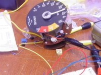
Here's a picture of the Smiths RVI rev-counter/tachmeter I'm using - it's from/for an MG I believe and it's part number is RVI 1433/01
I did some more reading, what I want is to add some kind of transistor buffer to the transconductance[url] amplifier - but my load is on the collector site of the transistor, no the emittor side. I'm guessing that doesn't matter as the datasheet example shows the load on the collector side (outside of the feedback loop) too.
Still stuck on the proper way to wireup what looks like a darlington pair...
Here's a picture of the Smiths RVI rev-counter/tachmeter I'm using - it's from/for an MG I believe and it's part number is RVI 1433/01
Attachments
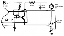
The external transistor forms a "darlington pair" with the transistor inside the chip. For the most part... the op amp won't know it's there. You will probably need to reduce the value of the pot under the emitter, use the equations in the data sheet; they will still hold true, you just won't have the current limitation of 50mA. Be sure to calculate the power for pot... worth a look at least. Pin 8 should go to B+. Otherwise all else remains the same. Be sure to use a TO-220 package style for the external transistor... it'll be packin' around Watt.
Attachments
Excellent! Thanks for that, I might jsut be getting this electronics lark.
I suggested that I might use a 6.2V (1W?? or more?) Zener to drop the power to the transistor thus keeping in within the power rating (.6W) - I guess I can try it and see if anything blows up?
Here's my thoughts:
Thanks for that, I might jsut be getting this electronics lark.I suggested that I might use a 6.2V (1W?? or more?) Zener to drop the power to the transistor thus keeping in within the power rating (.6W) - I guess I can try it and see if anything blows up?
Here's my thoughts:
Attachments
I've run it through the freeware version of b2spice, and I can't seem to get the transistor to dissipate more than ~450mw with a 14v feed.
I looked at the to92 packaged bc639 and that seems to be able to cope with a whole 830mw... which might mean that it's the way to go - it's also got a nice high voltage rating of something like 100V and peak current rating of 1.5A.
That said, if I drop the supply to a regulated 6V things look better again - however more parts req'd.
Time to put it on the breadboard again, and to see if I blow up any more chips and transistors.
Raro,
A couple of tweaks: First, I screwed up, and didn't use a true Darlington connection. Both emitter currents are passing through the resistor that creates the feedback for the op-amp; it's only fair that both collector currents pass through the gauge as well... picks up another 1-2% of accuracy,
Second, a rule of thumb for brain-less design is to divide data sheet maximums for current and power by 3-4. These specs are provided at Tambient of 25 C. That ambient goes away once the device is bundled up in an enclosure. I neglected to consider the emitter pot when doing the power calcs in my head... I think you'll be OK with the TO-92 package here. A nice day in OZ and the ambient will be 60 C inside the gauge housing. All in all a more brain-ful design.
Let us know he she works!
Attachments
I haven't had a huge amount of luck with this.
I'm not entirely sure whether
- it's my trigger circuit not being up to scratch (it's a 555 timer based thing) and not swinging above and below gnd (as seen at the lm2917n)
- or if the lm2917n is dead/faulty.
I seen to get a sane voltage out from the LM2917n (5-7.5v), but can't quite get the current working. At on/near 1ohm on the trimpot I get about 4ma, and any higher gives nothing - not quite what I'm after :\
I was sure that I had had it working off of the 555 timer based trigger previously, so I can't figure out why things are quite going to plan now.
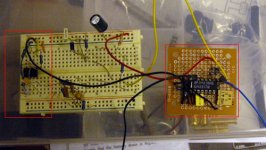
Okay - well that's all hunky dory, I left it running at 40ma for a few hours and it seems to still work.
The only downside is that it's not super stable at temperature the needle can drift about 500rpm - should I calibrate when hot, warm or cold? and is there a way of stabilising it?
The only downside is that it's not super stable at temperature the needle can drift about 500rpm - should I calibrate when hot, warm or cold? and is there a way of stabilising it?
Nothings really getting hot, or warm for that matter - I guess I meant hot/warm/cold as the length of time I'd left the circuit running.
Pic attached - am wondering whether I put in something like a to-92 or SMD voltage regulator - something like 8-9v.
The other weird thing I've noticed is that the 555 timer generates a pulse that is picked up by the tacho circuit through the ground. i.e. I disconnect the signal wire from the signal-out pin of the 555 the damn thing keeps going - disconnect the - or + from the 555 and it stops. Not really a bother - just a 'teacher why!?'. The circuit I used for it is similar to that found on this page - http://www.priory.bromley.sch.uk/students/electronics/reference/555astable.asp - but setup to provide about 66hz at a 50% duty cycle.
--edit eeek - forgot pic.
Attachments
You're probably right about the pot - it's a 25 turn type which I had hoped would be more stable, perhaps not? is there a better type - or do I need some other strategy (very exact resistor values?).
The 555 uses a 100nF mkt cap - you can just see it in the image:
The 555 uses a 100nF mkt cap - you can just see it in the image:
Attachments
poobah said:1) Get your circuit adjusted the way you want.
2) Measure the resistance of the pot.
...
Do you know how much power the pot is dissipating?
Nope - which raises a question. Will the meter with it's 13ohm resistance disipate most of the power? or will it be the transistor and resistor/pot? or are they all equal?
Yes - my basic electronics is pretty weak I'm afraid. The SPICE simulation I setup seemed to point to it all being high-ish - but it troubled me that the transistor at the base of the darlington pair disipated more power than the one that handled the current. Image attached.
Stocker said:It is much easier to wait for electronics to warm up than estimate how "cold" they are...
calibrate hot.
Ah yes - funny that - point taken
Attachments
OK...
My guess is that 1/2 Watt being dissipated in the pot is causing your stability problems. See the previous post.
You could verify the SIM just to be sure. The voltage across the 100 Ohm will tell you the current in that branch:
Current = Voltage / 100
Then measure the voltage across the pot:
Power = Current x Voltage
- Status
- This old topic is closed. If you want to reopen this topic, contact a moderator using the "Report Post" button.
- Home
- General Interest
- Everything Else
- Increasing the current max of an LM2917 Based Tachometer/Rev-counter