A pair of parallel wire will make a single loop and works as an antenna if exposed to magnetic field and an electric signal proportional to flux change will be present in loop circuit.
A pair of twisted wire will make many loops each of them working as an antenna but electric signal from any loop will cancel signal from next loop.
This is why on a balance system each pair of wire must de twisted, have a look on LAN wire you will see how it is done 8 wires twisted to make 4 pairs.
A pair of twisted wire will make many loops each of them working as an antenna but electric signal from any loop will cancel signal from next loop.
This is why on a balance system each pair of wire must de twisted, have a look on LAN wire you will see how it is done 8 wires twisted to make 4 pairs.
Twisting a balanced pair reduces the amount of electromagnetic induction, as the helix reduces the amount of conductor normal to the field, and so reduces the amount of noise induced. In balanced operation, this is 'balanced' out by the negative conductor, but the benefits of twisted pairs isnt limited to balanced cabling.
Ok?
Owen
Ok?
Owen
............... that's the bit I don't get.helix reduces the amount of conductor normal to the field
Pbassred said:............... that's the bit I don't get.
While the helix does indeed lower the total magnetic intercept cross section on a loop by loop basis, that is not why the twist works. For reaonable twist pitches, that reduction runs anywhere from 5% to 20% reduction.
As mentioned before, Faraday's law of induction applies. If you take a twisted pair, and project it's metal's "shadow" onto a surface, you will see the wire forms football (american, not the rest of the world) shaped openings. Note that the "positive conductor" in that pair swaps side to side, from one loop to the next.
When a changing magnetic field is going through those loops, each loop will produce a voltage, depending on the rate of change of the magnetic field, and the total area of each loop. The polarity of the voltage generated within each loop will depend on which side the "positive wire" is on. When it swaps side, the voltage polarity also swaps.
This causes the voltage that was generated loop to loop to be opposite sign, so they cancel.
Cheers, John
Had a pic, just couldn't find it...sorry..
Magnetic field will induce voltage in a loop of wire, the voltage is proprtional to the flux change in the loop ( farady,s law ) so for a flux change the voltage is proportional to the loop surface normal to the flux. Using twisted pair reduce surface and also give several surfaces opposite one to the other so several voltages oppotie one to the other this is why you get cancellation of the noise ( induced voltage )
Owen is right but you must use calculus to see how it is going when you read : the helix reduces the amount of conductor normal to the field
Owen is right but you must use calculus to see how it is going when you read : the helix reduces the amount of conductor normal to the field
janneman said:Hey John,
That means we should have an even number of twists, no ?")
Jan Didden
Odd you should say that, No?
If the magnetic field were uniformly changing along the entire pair length, yes, even would be required for complete cancellation.
Since most sources in the audio range are not uniform, but change in space, the effect would be localized to one area of a cable.
So, I would expect a distribution of generated voltages loop to loop looking somewhat like a sin x over x construct, x being distance along the cable.
Cheers, John
The possibility that you were being tongue in cheek did cross my mind, but I've never been one to consider common sense when posting..

Round the twist...
The two wires in the pair can only receive exactly the same noise (and therefore be cancelled) if they occupy the same point in space. A tight twist averages them to occupying the same point. If they were simply laid parallel, then one conductor would receive slightly more field (electrostatic or electromagnetic) than the other. Twisting alternates the positions so that they each receive equal interference.
In theory, that means you need an even number of twists (but see the previous post's comment). In practice, the wire is so short compared to the wavelength of the induced field (50Hz = 6000km) that it really doesn't matter. Even if the wire was 10km (not unheard of in the days of analogue telecommunications), then the slight imbalance caused by an extra twist that's a few inches long wouldn't matter.
Re: Round the twist...
Wavelength is not a consideration with twisted pairs for "space static" magnetic fields. Yes, it will be for fields which are propagating in space, as in radio.
I was speaking of fields which are not propagating per se, but are local phenomena, like the field generated by a transformer or degaussing coil or a length of romex.
We just gotta make sure we're talking apples and apples.
Cheers, John
EC8010 said:The two wires in the pair can only receive exactly the same noise (and therefore be cancelled) if they occupy the same point in space. A tight twist averages them to occupying the same point. If they were simply laid parallel, then one conductor would receive slightly more field (electrostatic or electromagnetic) than the other. Twisting alternates the positions so that they each receive equal interference.
In theory, that means you need an even number of twists (but see the previous post's comment). In practice, the wire is so short compared to the wavelength of the induced field (50Hz = 6000km) that it really doesn't matter. Even if the wire was 10km (not unheard of in the days of analogue telecommunications), then the slight imbalance caused by an extra twist that's a few inches long wouldn't matter.
Wavelength is not a consideration with twisted pairs for "space static" magnetic fields. Yes, it will be for fields which are propagating in space, as in radio.
I was speaking of fields which are not propagating per se, but are local phenomena, like the field generated by a transformer or degaussing coil or a length of romex.
We just gotta make sure we're talking apples and apples.
Cheers, John
Yes, I knew you had local sources like leakage from transformers and the like in mind; I was thinking of the rather more diffuse fields caused by power distribution, and, as you say, radio. It all goes to show that twisted pair is jolly good stuff.
I know what an apple is, but what's romex?
I know what an apple is, but what's romex?
EC8010 said:Yes, I knew you had local sources like leakage from transformers and the like in mind; I was thinking of the rather more diffuse fields caused by power distribution, and, as you say, radio. It all goes to show that twisted pair is jolly good stuff.
I know what an apple is, but what's romex?
Even the diffuse fields such as house wiring and power distribution can be picked up by small loop sizes. In fact, that is actually why hum exists at all.
Our enviro is such an e/m messy one. I'd prefer all ac distribution be carried out with coaxial wires to eliminate it. Course, that renders the handheld ac wire detectors useless, and I've been using one lately.. Boy, some people can really mess up house wiring...
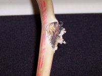
Romex is what we use this side of the pond to carry power in the walls of the house.
Here's a pic of romex.. this is actually a piece of what I found in the wall of my house. The "installation" goofball was putting a GFI in the bathroom, and in drilling to snake the wire, did this to the feed cable to the junction box...
Sheesh..
Cheers, John
Edit: that is what I found in the wall years after the work was done..I shoulda said "when he put it in"..
Attachments
There but for the grace of God...
Years ago, I was worried that I might manage the same trick, and I was alarmed that my power drill was not earthed. Technically, that was OK because the motor was double insulated, but the (metal) gearbox on the front would have been in very good contact with the cutting tip of the drill. I replaced the drill's cable and earthed the gearbox. I haven't yet managed to drill a cable, but if 30mA is needed to trip the RCD, I'd rather it went through a bit of wire rather than me.
Years ago, I was worried that I might manage the same trick, and I was alarmed that my power drill was not earthed. Technically, that was OK because the motor was double insulated, but the (metal) gearbox on the front would have been in very good contact with the cutting tip of the drill. I replaced the drill's cable and earthed the gearbox. I haven't yet managed to drill a cable, but if 30mA is needed to trip the RCD, I'd rather it went through a bit of wire rather than me.
On connecting a bipolar PSU... Do you twist together +V, -V and 0V, just +V and -V, or make two 0V leads to make +V and 0V, and -V and 0V leads?
Currenlty I use method A, but not based on any information other than readig about peolpe twisting cable, (heck I even googled and learned how to make braids with cables, never learned how in the more than 10 years I had long hair).
Currenlty I use method A, but not based on any information other than readig about peolpe twisting cable, (heck I even googled and learned how to make braids with cables, never learned how in the more than 10 years I had long hair).
It all depends on where the currents go. If you knew that the current only flowed from +ve to -ve (and never into 0V), then you'd twist +ve and -ve together, and ignore 0V. But the load (probably a loudspeaker) has one end connected to 0V, so there's load current in the 0V wire.
The braid versus two pairs of twisted wires is a good question. I think it's down to the class of output stage.
If you had a pure Class B output stage, you would know that load current flowed into the 0V wire from either the +ve or -ve, but never both simultaneously. In that case, the best solution would be to make a power supply with two transformer secondaries, two rectifiers, and two reservoir capacitors. You could then take a twisted pair from each and join the 0V from each supply at the loudspeaker GND terminal.
If you had a pure Class A output stage, you would know that load current supplied from one rail would be matched by an equal and opposite reduction in current in the other rail, so all three wires need to be twisted or plaited together.
In practice, power amplifiers are not usually pure Class A or B, but a mixture of both (Class AB) and the reason for twisting supply rails in a PSU is to reduce the interference it produces, rather than to protect it from interference. Twisting probably helps, but keeping the leads short and pushed into corners is likely to be more effective. On my rare forays into solid state, I twist or plait all three leads.

- Status
- This old topic is closed. If you want to reopen this topic, contact a moderator using the "Report Post" button.
- Home
- General Interest
- Everything Else
- How does Twisted pair work?