ron.eddy said:I feel that if you are already using a sufficient guage cable to connect your amp to your loudspeakers then bi-wiring is simply an act of overkill, and should not make too much of a difference. All you are doing is dividing up the current draw to 2x the cross-sectional area of wire, am I correct? And if the argument is that bi-wiring eliminates the interactions between the high and low or what have you frequencies why would this be the case at all? Unless you were biamping as well? I guess I am a little lost on all of this...
It does indeed get confusing..
Ok..first, consider the .1 ohm wire with a 1 ampere sine wave going through it. The dissipation when the sine is at the positive peak is, 1 squared times .1, or .1 watt...100 milliwatts. and, at the negative peak, again...100 milliwatts.
Now, increase the DC current on that wire until it is 1 ampere. the waveform now has 2 amperes as the peak current, and when the sine is at the negative peak, the wire has zero amperes current.
When the sine is at it's positive peak, the current is two amps total. The wire dissipates 2 squared times .1, or 400 milliwatts.
When the sine is at it's negative peak, there is no current. So, at this point there is no dissipation.
The introduction of the DC current has changed the amount of instantaneous power that has been dissipated within the wire that carries both the signals.
Is a distortion component that is 3.7% of the signal considered audible?
The amplifier has zero output impedance, and it is a voltage source..so where does that extra power at the positive peaks come from?
Note that the substitution of the single .1 ohm wire by two independent .2 ohm wires, or even two .1 ohm wires, does not create the same dissipation as the one wire with the two signals..
We are talking about two 8 watt signals here, the difference in dissipation between the dc signal on and off (.3w) represents 3.7% of the total power signal.
Hey, maybe I did the math wrong?? Then again, maybe not?

Cheers, John
Re: Re: biwire followup..
No. Assume that the amp out is either the sine, or the offset sine.
The single wire feeding a multiple branch splitter is what is causing the dissipation variation.
For multiple signals that all go to the same branch, the loss in the wire is exactly a fraction of the load power dissipation, so no other dissipation components show up.
This shows that the crossover must go at the amp terminals, with individual wires to each driver.
Of course, it is much simpler to re-calculate the wire guage minimum for percentage distortion vs wire run...as the current tables used are only fraction of power lost by IR.
Cheers, John
ron.eddy said:
I am sorry, maybe I am having a bad day, but I don't understand this either. What does this show? These signals would have been combined at the amplifier anyway, so biwiring them would not separate them and result in such dramatically lower losses... It would only lower the losses by how much less resistance the signal would see, since you are doubling the available wire. This would not amount to too much savings (well with 18 ga. running 16 feet it may) but not if you already have a good sized wire.
Wait a minute, what the heck is bi-wiring? Maybe I have it all mixed up.
No. Assume that the amp out is either the sine, or the offset sine.
The single wire feeding a multiple branch splitter is what is causing the dissipation variation.
For multiple signals that all go to the same branch, the loss in the wire is exactly a fraction of the load power dissipation, so no other dissipation components show up.
This shows that the crossover must go at the amp terminals, with individual wires to each driver.
Of course, it is much simpler to re-calculate the wire guage minimum for percentage distortion vs wire run...as the current tables used are only fraction of power lost by IR.
Cheers, John
How hard can it be to find out if burning in has any effect?
Take two identical, brand new pieces of equipment, that are supposed to benefit from burn in. Listen to them and confirm you can't hear any difference. Then burn in one of the pieces, but not the other one. After that, perform a DBT.
Of course, this assumes that brand new equipment of the choosen type are not audibly different, which could be a problem, perhaps. However, there ought to be a lot of equipment that would sound identical in a DBT.
Re burn-in, I once replaced two 2uF mylar for metallized polypropylene capacitors in the reference AC circuit board of an Elgar line conditioner. The reference board in the Elgar generates a reference AC signal that is summed with the output of the unit as taken through a resistor; the remainder---the difference, essentially, between the reference and the output---is amplified as NFB to reform the output AC to match the reference sine. After swapping out the mylars, the Elgar generated a serious 15V spike on its output.  This spike reduced over the course of two days and finally disappeared. Of course, being the non-scientist I am, I thought the sound of my audio system, fed by the Elgar, sounded worse before the spike disappeared, but sounded better than the mylar-Elgar once the spike disappeared.
I have two Elgars operating in my system. I replaced the mylar caps in Elgar #2 with metallized polypropylenes (same make as went into Elgar #1). Elgar #2 then generated the same fright spike, which then slowly disappeared as the new capacitors ..... drum roll ..... broke in.
This spike reduced over the course of two days and finally disappeared. Of course, being the non-scientist I am, I thought the sound of my audio system, fed by the Elgar, sounded worse before the spike disappeared, but sounded better than the mylar-Elgar once the spike disappeared.I have two Elgars operating in my system. I replaced the mylar caps in Elgar #2 with metallized polypropylenes (same make as went into Elgar #1). Elgar #2 then generated the same fright spike, which then slowly disappeared as the new capacitors ..... drum roll ..... broke in.
Is a distortion component that is 3.7% of the signal considered audible?
But it isn't really a distortion component, is it? If we assume a very low inductance/capacitance in the wire, relative to its resistance, it would simply be a 3.7% attenuation, would it not? Since resistance is not dependent on frequency, the whole signal, sine wave and DC will be attenuated power wise by 3.7% so that the power into the load will equal power delivered by amp minus the power dissipated by the wire as heat.
That graph is absolutely correct in that a sine wave on its own on that wire will have a dissipation four times less than with both (assuming 1A signals) since (1+1) squared is 4 and 1 squared is 1.
But yea, I think we are agreeing now that I read through it all, I was just confused to all hell for a while there. It would be much simpler to calculate out a bigger guage wire and not worry about putting the xover right at the amp.
----------------------------------------------------------------------------------------
As for burn-in how would this work physically? I have had many audio product (non mechanical such as speakers) that I did not like at first but after it burned in I swore it sounded better. But I keep doubting myself because I cannot explain it. The caps should form within seconds of first power on (although reading the above post makes me reevaluate that opinion), the resistors and inductors are wires, the silicon is a pure element doped with molecules which are all made of the same bits of protons and electrons, forming depletion regions and moving holes and electrons around at will. What in there would cause any solid state electronic device to need a break-in? (Mind you I am neither denying or supporting it, I am curious is all)
- Ron
Just a couple short notes on each of the myths:
1. The Cable Lie - Not gonna touch this one here.
2. The Vacuum-Tube Lie - Nope, not this one either.
3. The Antidigital Lie - I do see where he is coming from in a way, but for him to say (referring to 44,100 hertz sampling) "It will not cause any loss of information in the audio range—not an iota, not a scintilla", if I were to believe it, would lead me to the natural question that comes of it: Why do we now have 96kHz sampling rates? Bet he can't answer that.
4. The Listening-Test Lie - This I agree with, I wish tests which are then published or even put on good looking websites would be more consistent and formal.
5. The Feedback Lie - No comment, I have not gained enough experience.
6. The Burn-In Lie - I would like to find out about this one.
7. The Biwiring Lie - Still confused...
8. The Power Conditioner Lie - I agree with this to a point as well, unless your house has really bad power quality for some reason.
9. The CD Treatment Lie - I have never heard of this stuff but if someone somewhere says it makes a difference in the sound they are, unequivocally, crazy.
10. Golden Ears - Ah yes, as GRollins pointed out, the better educated your ears are the better you'll hear all those expensive circuits you've been working on in your basement
- Ron
ron.eddy said:
But it isn't really a distortion component, is it? If we assume a very low inductance/capacitance in the wire, relative to its resistance, it would simply be a 3.7% attenuation, would it not? Since resistance is not dependent on frequency, the whole signal, sine wave and DC will be attenuated power wise by 3.7% so that the power into the load will equal power delivered by amp minus the power dissipated by the wire as heat.
ARRRGGGGGHHHHH

No,no.no,no...(he he, just funnin ya..)
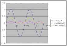
Seriously...look at the graph again. For the single sine wave signal in the wire, the dissipation is a function of frequency times two (blue)...but with the offset sine, the bulk of the dissipation is a function of frequency. So the loss is NOT of the same spectra as either of the branch dissipations.
the math gets worse if you add two sines of different frequencies, for the 2AB thing is the multiplication of two sines. And then, three loads??
OH...I almost forgot...What happens when both channels have the hf signal, say a voice, or a bell, at center stage, equal intensity, and then an equal sized bass note occurs in one channel only? Does the 3.7% error in power being delivered to the channel with the bass note cause the center image to shift away from the bass? Hmmmm.
Yup.ron.eddy said:That graph is absolutely correct in that a sine wave on its own on that wire will have a dissipation four times less than with both (assuming 1A signals) since (1+1) squared is 4 and 1 squared is 1.
Confusion is a way of life for me..ron.eddy said:
But yea, I think we are agreeing now that I read through it all, I was just confused to all hell for a while there. It would be much simpler to calculate out a bigger guage wire and not worry about putting the xover right at the amp.
- Ron
This incredibly crude and simple analysis points out the need to revisit the wire guage vs wire length, and can be done for specific distortion figures..for example, 8 ohm, 16 feet, 4% max distortion, two way crossover, ya need #18 or better wire. I won't even touch on how the dissipation error causes the shifting of virtual images within the soundstage as a result of the power modulation caused by the crossover branches..
Cheers, John
as to what effect burn in has in terms of being audible or not
perhaps many experts here would agree that objectivism could
show that to be the case or not, how do you define burn-in and
what purpose it has is another matter, for example some equipement take time to settle in while others take less, and to
some burn-in is just a test at the end of manufacture
regards
Seriously...look at the graph again. For the single sine wave signal in the wire, the dissipation is a function of frequency squared (blue)...but with the offset sine, the bulk of the dissipation is a function of frequency. So the loss is NOT of the same spectra as either of the branch dissipations.
Clearly I am in over my head. I know the sine wave is a function of frequency but how is power a function of frequency? But maybe this is where I got confused, as I have been talking about the rms power this whole time, which is not a function of frequency and no matter what signal you have, it can be broken into sine waves and using superposition can be analyzed, therefore the currents all added up will still not be frequency dependent (rms). A 20khz sine wave going through a non-inductive, non reactive load will dissipate the same power as a 60Hz wave through the same resistor, right (same amperage for each of them of course)? Throw in those pesky inductances and capacitances of the cable and THEN I quit! Hehe
So what you are asking about is the dissipation at the peaks of those sine waves and how they compare with individual branches and where that extra power comes from and how bi-wiring helps (or does help)? Haha, I am gonna swallow my pride fully and say I have no idea what we are talking about anymore. I don't think I know as much about AC waveforms as I should. I have a bunch of papers in front of me I have been scribbling calculations on to try to understand, but alas, haha
.It will not cause any loss of information in the audio range—not an iota, not a scintilla
Yes, well, energy can neither be created or destroyed. Its all there, all 5 dynamically overcompressed bits of it, but is there any, say, for example, phase shift?
ron.eddy said:
Clearly I am in over my head. I know the sine wave is a function of frequency but how is power a function of frequency? But maybe this is where I got confused, as I have been talking about the rms power this whole time, which is not a function of frequency and no matter what signal you have, it can be broken into sine waves and using superposition can be analyzed, therefore the currents all added up will still not be frequency dependent (rms). A 20khz sine wave going through a non-inductive, non reactive load will dissipate the same power as a 60Hz wave through the same resistor, right (same amperage for each of them of course)? Throw in those pesky inductances and capacitances of the cable and THEN I quit! Hehe
So what you are asking about is the dissipation at the peaks of those sine waves and how they compare with individual branches and where that extra power comes from and how bi-wiring helps (or does help)? Haha, I am gonna swallow my pride fully and say I have no idea what we are talking about anymore. I don't think I know as much about AC waveforms as I should. I have a bunch of papers in front of me I have been scribbling calculations on to try to understand, but alas, haha
Welcome to my world dude. You have no idea what it's like for me at work. In the 13 years I've been here, I am now capable of pronouncing half the words they use here. I figure that I'll know maybe 75% of the words..by the time I retire.
Ah, I see your confusion..no I am not talking about the integrated losses, but the instantaneous ones.
A simple sine wave has both a positive and negative peak. Power is the square of that sine, and squares cannot be negative here..so the blue line on the graph shows twice the frequency, but with a dc offset. I see where I messed up, I did not include the simple sine wave for reference..here it is.
Sorry for changing colors on ya, excel...
Ok...now, the sine wave is blue..provided for reference. It is amperes...The magenta line is the current squared times .1, so it is in watts. Note that when you square the negative lobes of the sine, the result is positive.
The yellow line is the result of the offset sine when you square it. As you can see, it has the same period as the fundamental sine wave.
The introduction of the dc offset signal has caused the loss in the wire to morph from the magenta waveform, to the yellow one.
That is the difference a biwire setup removes..
THAT difference must be tested as to audibility.
Cheers, John
Attachments
Without commenting on actual audibility of 48/96 i can see it asron.eddy said:Just a couple short notes on each of the myths:
Why do we now have 96kHz sampling rates? Bet he can't answer that.
- Ron
marketing department numbers game. Why do we have cars with over 200km/h top speed if maximum speed limit on public roads is 120km/h? Why do we have 400hp car engines when 40hp would be enough to carry 4 persons over 120km/h?
Or why do we have 4 megapixel sensors on cellphone cameras even that lens is limiting resolution to 1 megapixel and noise from 4 megapixel sensor makes it actually worse and less usefull than 1 mpix sensor?
LOL. I see now. WOW.
Yea, I think it may be easier to just recalculate wire run/wire gauge, since most of the time the crossover is already in the speaker. Although you could get really crazy and build all your crossovers and amps into one enlosure custom made for your speaker set. I don't know how practical that would ever be...
And your bell/bass question is an intriguing one. Hopefully if everything is calculated right you shouldn't have these errors in such a degree where it would effect the audible sound, but perhaps it does, in that case you may have just come up with a measurement to go along with the thought that these things make a difference.
- Ron
mzzj said:
Without commenting on actual audibility of 48/96 i can see it as
marketing department numbers game. Why do we have cars with over 200km/h top speed if maximum speed limit on public roads is 120km/h? Why do we have 400hp car engines when 40hp would be enough to carry 4 persons over 120km/h?
Or why do we have 4 megapixel sensors on cellphone cameras even that lens is limiting resolution to 1 megapixel and noise from 4 megapixel sensor makes it actually worse and less usefull than 1 mpix sensor?
Very true, very true, I just wonder because to me and to my ears it SEEMS as though DVD's sound quite a bit better than CD, but again it could definitely be a combination of things like the studio equipment used to record the sound being better, the production, the A/D converter quality and then the D/A converter in my unit. So its another one of those catch-22 questions, since it can always be answered by spinning it on other things.
But yea, good point.
I found this at MathWorld:
In order for a band-limited (i.e., one with a zero power spectrum for frequencies nu>B) baseband (nu>0) signal to be reconstructed fully, it must be sampled at a rate nu>=2B. A signal sampled at nu==2B is said to be Nyquist sampled, and nu==2B is called the Nyquist frequency. No information is lost if a signal is sampled at the Nyquist frequency, and no additional information is gained by sampling faster than this rate.
So I am wrong, there is no benefit to higher than 44kHz (actually 40kHz would be sufficient), given that they chop the sound off at 20khz anyway. Now if they would only chop the sound at 48kHz instead when using 96k sampling maybe there would be a difference, since those higher order harmonics would still be in the signal, as they were when it was originally sang (or played, or beat on, or however the sound was created)
8. The Power Conditioner Lie
Just about all that needs to be said on
this subject has been said by Bryston in
their owner’s manuals:
“All Bryston amplifiers contain
high-quality, dedicated circuitry in the
power supplies to reject RF, line spikes
and other power-line problems. Bryston
power amplifiers do not require specialized
power line conditioners. Plug the
amplifier directly into its own wall
socket.”
What they don’t say is that the same
is true, more or less, of all well-designed
amplifiers. They may not all be the Brystons’
equal in regulation and PSRR, but
if they are any good they can be plugged
directly into a wall socket. If you can afford
a fancy power conditioner you can
also afford a well-designed amplifier, in
which case you don’t need the fancy
power conditioner. It will do absolutely
nothing for you.
The biggest and stupidest lie of
them all on the subject of “clean” power
is that you need a specially designed
high-priced line cord to obtain the best
possible sound. Any line cord rated to
handle domestic ac voltages and currents
will perform like any other. Ultrahigh-
end line cords are a fraud. Your
audio circuits don’t know, and don’t
care, what’s on the ac side of the power
transformer.
On this one I would agree with him.
Fact is I have never ever invested in anything on Mains AC side
to get better audio performance.
An ordinary small LC filter at mains AC input of amplifier.
This is all.
Any good amplifier will have this.
Otherwise I would put it in myself.
You can find readymade AC inlets that have this filter.
Most used is a dual coil and 2 or 3 capacitors rated for mains use.
There has been no research that I know of
that has shown what comes in at mains voltage
will effect what comes out of amplifiers,
and so even less likely it can pass loudspeaker coil.
I would say,
if this is the case,
power supply in ampifier is of the worst sort
and who did it, doesnt know elementary supply basics.
John,
I think are onto something here... perhaps if you were greedier you wouldn't air it here.
Your basically saying that a higher frequency wave is being disproportionately robbed off power when it is riding the peak of a lower frequency wave?
Hmmmm....................
I am running sims here as well.
This is akin in some ways to the doppler effect imposed on higher frequencies emitting from a diaphram primarily moving with a lower frequency.
Yes, it's far better to just go heavier on the wire.ron.eddy said:LOL. I see now. WOW.
Yea, I think it may be easier to just recalculate wire run/wire gauge, since most of the time the crossover is already in the speaker. Although you could get really crazy and build all your crossovers and amps into one enlosure custom made for your speaker set. I don't know how practical that would ever be...
It does, however, point to the possibility that bi-wiring is indeed justifiable, and really silly guage wires like #6 or 8 for low impedance multiway systems is justified.
ron.eddy said:
And your bell/bass question is an intriguing one. Hopefully if everything is calculated right you shouldn't have these errors in such a degree where it would effect the audible sound, but perhaps it does, in that case you may have just come up with a measurement to go along with the thought that these things make a difference.
- Ron
Once the effect is more fully understood, it will be trivial to calculate out the guage required to remain below some threshold of distortion.
The easy thing about this analysis is that by using DC as the second signal, it is trivial to look at the hf signal at the "driver", or dummy load, and look for shifts in the waveform. An easy thing to do would be have two cables side by side into two two way crossovers, and inject a dc bias into one side, using a differential comparison of the hf signal at the load. Even put a half or 1 hz square wave into one side to look for the change..
Alas, I don't think anyone here will take the time or effort to try the test...sigh.
Can't wait for my basement to be complete.
Cheers, John
ps...I'm tossed as to whether or not to engage in the power conditioner point..maybe next year..
Theres one thing that can be noticed by most amps that we'd call "good" on the AC line, but no power cord will fix. DC.
Have you driven a fully loaded VW Beatle lately?
It might not just be the better sampling rate your hearing, it could also be the bitrate. 16 bits might be "good enough", but not if you throw 7 away for loudness.
Why do we have 400hp car engines when 40hp would be enough to carry 4 persons over 120km/h?
Have you driven a fully loaded VW Beatle lately?
It might not just be the better sampling rate your hearing, it could also be the bitrate. 16 bits might be "good enough", but not if you throw 7 away for loudness.
It's not breaking the laws of superposition, it's not some new physics.... and contrary to what he said, I am not going to be "an instant candidate for some truly major scientific prizes and academic honors.."..all that verbage is is just blustery yada yada in the attempt to justify his "analysis" so to speak..poobah said:John,
I think are onto something here... perhaps if you were greedier you wouldn't air it here.
poobah said:Your basically saying that a higher frequency wave is being disproportionately robbed off power when it is riding the peak of a lower frequency wave?
It would appear that that is the case..I've wrung my brain cells over what could possibly be incorrect with my analysis, as well as speaking of this to a few of my collegues here, but I've not found anything wrong yet...there may be, I just haven't found it..
It just seems so trivially simple to have been overlooked for so many years..
Hmmmm....................
poobah said:I am running sims here as well.
Good. Independent verification is a wonderful thing. Test verification will also have to be done as well.
I've already worked out those details..
Cheers, John
- Status
- This old topic is closed. If you want to reopen this topic, contact a moderator using the "Report Post" button.
- Home
- General Interest
- Everything Else
- 'Audio Lies'