Why?phase_accurate said:Ask him
Regards
Charles
He confuses linearity of superposition with power loss through a conductor feeding a two or three branch system via a single node..
The article is rant fodder. a mix of correct and incorrect. I was hoping someone here could speak a little more eloquently..
Cheers, John

jneutron said:I was hoping someone here could speak a little more eloquently.
John,
We rely heavily on you to add eloquence to the convoluted explanations.
Then you are in trouble..Cal Weldon said:John,
We rely heavily on you to add eloquence to the convoluted explanations.
 I seem to only add to the convolution..
The power dissipation within a resistor is P = I2R.
Assume a two way crossover, 8 ohm independent loads, two sine waves, each directed to it's driver.
The current within the cable is A plus B, A being sin(2 pi 50 t), B being sin(2 pi 5000 t).
The power dissipated within the cable is:
Pc = I2Rc
Pc = (A + B)2Rc
(A + B)2 = A2+ B2 + 2 AB.
Pc = (A2+ B2 + 2 AB)Rc
Pwoofer = A2R
Ptweeter = B2R
As can be seen, the wire has an additional component of dissipation, the 2AB component, whereas the loads each have only the A or B squared component.
So where is the power that is represented by that 2AB coming from?? And, why is it different from what is being dissipated at the loads?
Cheers, John
Here guys... tear this to shreds:
http://www.st-andrews.ac.uk/~www_pa/Scots_Guide/audio/biwire/Page3.html
http://www.st-andrews.ac.uk/~www_pa/Scots_Guide/audio/biwire/Page3.html
poobah said:Here guys... tear this to shreds:
http://www.st-andrews.ac.uk/~www_pa/Scots_Guide/audio/biwire/Page3.html
Read it years ago.
Note this:
If the sound power produced depends upon the square of the current fed to the system, this implies that the frequency response may perhaps be changed by bi-wiring as a result of interactions between the choice of cabling arrangement and the input impedances/networks of the loudspeaker units.
Well, the square part is correct. Unfortunately, he does not delve into the instantaneous power dissipation of the conductor for offset sines.
Hopefully, in the future, he will correct his article..
Cheers, John
PS..his skin theory article math is to die for..very well done.
SY said:But they're no more often right than a coin flip.
And how would you *know* that, SY? (I love how the science just fades away for certain purposes.) I'd say SY's statement is as improbable as Robert Partker or Hugh Johnson's views on various wines being no more probable than a coin flip.
Hugh Johnson makes his money telling other's what tastes good... his service may be valuable to those who share his opinions and especially trust his tastebuds more than their own. Wine remains art, its beauty belonging to the beholder.
Audio reproduction is about just that... reproduction... less room for artistic interpretation... or at least that's how it should be.
Are's SY's observations less credible because he isn't paid for them?
Audio reproduction is about just that... reproduction... less room for artistic interpretation... or at least that's how it should be.
Are's SY's observations less credible because he isn't paid for them?
biwire followup..
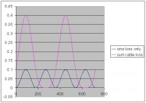
Here's the dissipation that occurs within a wire of .1 ohm total loop resistance for two cases...one case is the sine wave by itself, that is the blue line..the second is the sine wave added to a dc current. This case represents an offset sine being fed into 16 feet of #18 wire terminated in a crossover feeding two 8 ohm loads, 1 ampere drives.
Note the discrepencies between the two??
Now, why is Bi-wiring a sham??
Cheers, John
PS..horiz axis is degrees.
Attachments
serengetiplains said:
And how would you *know* that, SY?
Cogito, ergo agnosco bs.
serengetiplains said:(I love how the science just fades away for certain purposes.)
'Ouch' was my third response. The first was eaten by a brownout, the second I just got tired, but essentially both said the same as you in regard to earlier posts, specifically the notions that reviewers rate equpiment in dark cases dark sounding and bright as bright, and that break-in is acclimation. The most cursory examination of three decades of Stereophile and Absolute Sound renders the first conjecture obviously untrue. Start by examining reviews of Audio Research and Conrad Johnson gear and demonstrate they're consistently described as brighter than the black Rotels, Adcoms, and other solid state gear of the period.
As per break-in, it's my recollection that most every reviewer takes it as a given - for example when reviewing speakers, arguably the most relevant circumstance - and run-in equipment un-auditioned and outside their main system before review. At most they'll do a cursory listen beforehand. Speakers are also often compared directly against familiar references or other models in the same price bracket afterwards to assess overall value. They're not listening during the break-in period, and post-comparison would quickly reveal if the perceived change was due to acclimation.
Again, this isn't to say reviewers are honest, intelligent, or have no involvement with the general Decline of Western Civilization or Hoffa's disappearance. It is to say that the rationalizations presented here in the name of science aren't based on the written evidence. At best they're uninformed conjectures, but not science.
jneutron said:
The power dissipated within the cable is:
Pc = I2Rc
Pc = (A + B)2Rc
(A + B)2 = A2+ B2 + 2 AB.
Pc = (A2+ B2 + 2 AB)Rc
Pwoofer = A2R
Ptweeter = B2R
As can be seen, the wire has an additional component of dissipation, the 2AB component, whereas the loads each have only the A or B squared component.
So where is the power that is represented by that 2AB coming from?? And, why is it different from what is being dissipated at the loads?
Forgive me, but I am a little confused by what you are saying, since A2+ B2 + 2 AB has no extra components versus A2R or B2R when you take into account that you are comparing a lumped together square versus individual squares... After all, (5 + 5) squared will always be bigger than 5 squared plus 5 squared (by an amount that happens to be 2*5*5 (2AB in this case). Or perhaps I don't understand what you mean. Without bi-wiring, the cable going from the amp to the speakers would have a current of A+B, with each current getting split into its own driver after the crossover, resulting in say A at the tweeter and B at the woofer. Lets assume the crossover splits the amperage directly in half for simplicity sake, you would then have (A+B)/2 at each driver.
While (A+B)/2 + (A+B)/2 does indeed equal the current coming in at (A+B), the same cannot be said for the squares, as if you added up the power individually:
R * ((A+B)/22 + (A+B)/2)2) it would not be equal to R * (A+B)2
And if you think about it in real terms, with your math you are squaring the total current to get the power dissipated by the cable and squaring the individual currents to get the power dissipated by the drivers, and there is no law that says power dissipated must be equal between components, just the amperage. The power is all variant on the load. Numerically it wouldn't make sense either since if A was 4 amps and B was 2 amps, you would know 2 amps goes to the tweeter and 4 amps goes to the woofer, each having their own unique power dissipation based on their load. The 6 amps going through the initial conductor may as well just be another variable, like C, so then you would have:
Pc = C2*Rc
Ptweeter = B2*Rb
Pwoofer = A2*Ra
Now there is no additional component, and A, B, C are all different anyway. In the case of the power dissipated it is irrelevant that C = A+B because of the squaring.
Forgive me if I completely misinterpreted your point.
I feel that if you are already using a sufficient guage cable to connect your amp to your loudspeakers then bi-wiring is simply an act of overkill, and should not make too much of a difference. All you are doing is dividing up the current draw to 2x the cross-sectional area of wire, am I correct? And if the argument is that bi-wiring eliminates the interactions between the high and low or what have you frequencies why would this be the case at all? Unless you were biamping as well? I guess I am a little lost on all of this...

Re: biwire followup..
I am sorry, maybe I am having a bad day, but I don't understand this either. What does this show? These signals would have been combined at the amplifier anyway, so biwiring them would not separate them and result in such dramatically lower losses... It would only lower the losses by how much less resistance the signal would see, since you are doubling the available wire. This would not amount to too much savings (well with 18 ga. running 16 feet it may) but not if you already have a good sized wire.
Wait a minute, what the heck is bi-wiring? Maybe I have it all mixed up.
jneutron said:Here's the dissipation that occurs within a wire of .1 ohm total loop resistance for two cases...one case is the sine wave by itself, that is the blue line..the second is the sine wave added to a dc current. This case represents an offset sine being fed into 16 feet of #18 wire terminated in a crossover feeding two 8 ohm loads, 1 ampere drives.
Note the discrepencies between the two??
Now, why is Bi-wiring a sham??
Cheers, John
PS..horiz axis is degrees.
I am sorry, maybe I am having a bad day, but I don't understand this either. What does this show? These signals would have been combined at the amplifier anyway, so biwiring them would not separate them and result in such dramatically lower losses... It would only lower the losses by how much less resistance the signal would see, since you are doubling the available wire. This would not amount to too much savings (well with 18 ga. running 16 feet it may) but not if you already have a good sized wire.
Wait a minute, what the heck is bi-wiring? Maybe I have it all mixed up.
- Status
- This old topic is closed. If you want to reopen this topic, contact a moderator using the "Report Post" button.
- Home
- General Interest
- Everything Else
- 'Audio Lies'