Hello friends.
i have a 1WATT FM Transmitter schematic, to which i design a PCB using Express PCB soft..
at the test, transmission clairity is very good but only for an OVER THE AIR distance of 50-55 mtrs max.. surely much less than my expectation of around 500-600 mtrs atleast...
i used a dipole antenna for transmission with a decent RG8 cable. And the class C amplfier 2N3866 doesnt disspiate significant amount of heat. using a scope i observe no amplification of the osc. freq. arcoss its o/p.. can anyone suggest some modifications to be to the design..
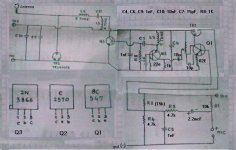
i have posted the blurred schematic of my Tx.. I feel the need for greater inductance across Class C biasing.. and removing Trimmer 2; the one just before the Tx o/p..
Please advice..
________________
Prasanna.
Expectation leads to disappointment...
More expectations lead to more disapoinments.
i have a 1WATT FM Transmitter schematic, to which i design a PCB using Express PCB soft..
at the test, transmission clairity is very good but only for an OVER THE AIR distance of 50-55 mtrs max.. surely much less than my expectation of around 500-600 mtrs atleast...
i used a dipole antenna for transmission with a decent RG8 cable. And the class C amplfier 2N3866 doesnt disspiate significant amount of heat. using a scope i observe no amplification of the osc. freq. arcoss its o/p.. can anyone suggest some modifications to be to the design..
i have posted the blurred schematic of my Tx.. I feel the need for greater inductance across Class C biasing.. and removing Trimmer 2; the one just before the Tx o/p..
Please advice..
________________
Prasanna.
Expectation leads to disappointment...
More expectations lead to more disapoinments.
Attachments
Sir,
The total dipole length is around 2 meters (1 + 1 mtr). Impedance of the cable is 75 Ohms, as rated with the o/p impd. of the transmitter.. The tx. is tuned to freq. of 102.3 MHz.
And if i use a simple 100cm aerial, then too the range is around 15-20 meters.. not much diff. as compared to the dipole range..
________________
Some thoughts: Wavelength at 100 MHz is 3 meters approx so a half-wavelength dipole is 1.5 meters and a quarter-wavelength aerial is around 75 cm.
When using the dipole then use is vertically, since your receiver's antenna is most probably also vertically polarised.
Have you ever checked the output power of your TX into a resistive load ?
Regards
Charles
When using the dipole then use is vertically, since your receiver's antenna is most probably also vertically polarised.
Have you ever checked the output power of your TX into a resistive load ?
Regards
Charles
- Status
- This old topic is closed. If you want to reopen this topic, contact a moderator using the "Report Post" button.